Ar135
Members
-
Joined
-
Last visited
Everything posted by Ar135
-
Problem resolved, after the reset the Modbus SN was changed to 00, changed it to 01, restarted the inverter and all readings are back to normal.


-
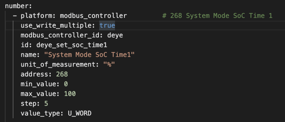
Hi All, I've had my system running for months now and it's been fine. Today we installed another battery and had issues with the Deye 5.5KW recognising both new and old batteries. After much troubleshooting we had Deye upgrade the firmware of the unit, that fixed the battery issues, then the integration issues started! At first the ESP would connect and read, but all the data had NaN values. Dug around on the inverter itself and the Modbus was changed from 01 to 00, must have happened when the new firmware was installed. Changed that in the code and it started reading again. Now the problem is this: It's not reading the time zone values, only displaying 21474 and also not displaying the SOC% only NaN. What do I do to fix this? Example of the Write settings:
-
I"m pretty sure it's the RS485 port.
-
I had the same issue, remove the VCC from the esp32 and it worked. check here:
-
@frankthetank No power to the RS485 only GND. When I had the red and black I got nothing but errors, I accidentally removed the red and it started reading! I also have Brown/White & Orange connected to 1 and Orange/White & Brown connected to the other with the R7 removed, all connected to a Deye 5KW so I'm not sure if there's going to be a difference.

-
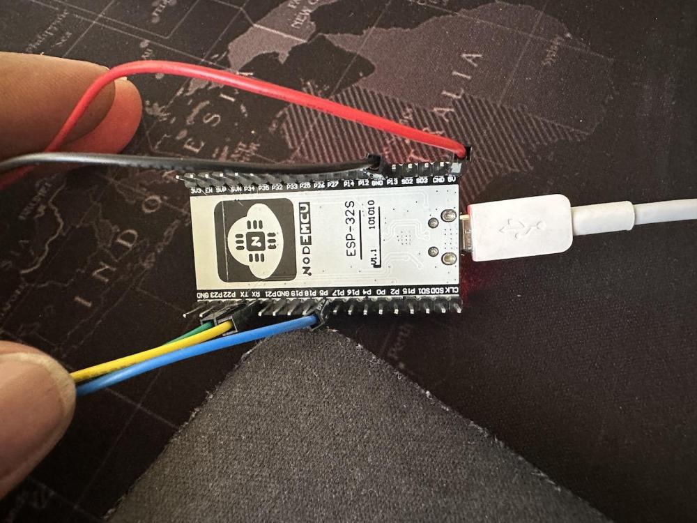
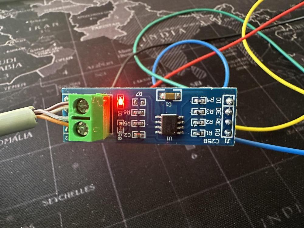
I Fixed it! (sort of) Somehow the connections on the RS485 board came loose, so I reconnected it and it's reading again! Here's my connections Black wire is GND Blue is Pin5 > RE Yellow is RX > R0 Green is TX >DI Code on the ESP32 - uart: id: mod_bus tx_pin: GPIO1 rx_pin: GPIO3 baud_rate: 9600 stop_bits: 1 modbus: id: deye_modbus flow_control_pin: GPIO5


-
I followed @Sc00bs video and got it working, and it's been working for a while, today I updated ESPHome to 2023.9.0 and it broke! I now keep getting this: I've reverted ESPHome to 2023.8.3 and reloaded the board, and it's still not reading, doesn't make sense! Next step is to revert Home Assistant to a previous backup. (Will advise if that fixes it) Anyone have any ideas what to look for?

-
THANKS!!!!! I swopped A & B around, but that didn't work. What did work was the VCC cable was unplugged and it started pulling data! When i connected the VCC again it stopped! Now the question is, do I need the GND and 5V connected on the RS485? Well I answered my own question. If I disconnect the GND I get CRC errors. This is what it looks like now: ESP32: RS485 Front: RS485 Back Also I need to setup the correct registers and then I'm all good! Any idea who's repo I can use for the Deye 5.5KW? I'm doing this for a 8KW next week, do you think the same connections will work? Thanks again for the help!!!


-
Hi Guys I'm having a similar problem. My inverter: Deye 5.5KW inverter I get this: INFO ESPHome 2023.6.3 INFO Reading configuration /config/esphome/esphome-web-9c4334.yaml... INFO Starting log output from esphome-web-9c4334.local using esphome API INFO Successfully connected to esphome-web-9c4334.local [11:32:38][I][app:102]: ESPHome version 2023.6.3 compiled on Jun 30 2023, 10:52:22 [11:32:38][C][wifi:543]: WiFi: [11:32:38][C][wifi:379]: Local MAC: [redacted] [11:32:38][C][wifi:380]: SSID: [redacted] [11:32:38][C][wifi:381]: IP Address: [redacted] [11:32:38][C][wifi:383]: BSSID: [redacted] [11:32:38][C][wifi:384]: Hostname: 'esphome-web-9c4334' [11:32:38][C][wifi:386]: Signal strength: -81 dB ▂▄▆█ [11:32:38][C][wifi:390]: Channel: 6 [11:32:38][C][wifi:391]: Subnet: 255.255.255.0 [11:32:38][C][wifi:392]: Gateway: [redacted] [11:32:38][C][wifi:393]: DNS1: [redacted] [11:32:38][C][wifi:394]: DNS2: [redacted] [11:32:38][C][logger:301]: Logger: [11:32:38][C][logger:302]: Level: DEBUG [11:32:38][C][logger:303]: Log Baud Rate: 0 [11:32:38][C][logger:305]: Hardware UART: UART0 [11:32:38][C][uart.arduino_esp32:124]: UART Bus 0: [11:32:38][C][uart.arduino_esp32:125]: TX Pin: GPIO1 [11:32:38][C][uart.arduino_esp32:126]: RX Pin: GPIO3 [11:32:38][C][uart.arduino_esp32:128]: RX Buffer Size: 256 [11:32:38][C][uart.arduino_esp32:130]: Baud Rate: 9600 baud [11:32:38][C][uart.arduino_esp32:131]: Data Bits: 8 [11:32:38][C][uart.arduino_esp32:132]: Parity: NONE [11:32:38][C][uart.arduino_esp32:133]: Stop bits: 1 [11:32:38][C][modbus:143]: Modbus: [11:32:38][C][modbus:144]: Flow Control Pin: GPIO5 [11:32:38][C][modbus:145]: Send Wait Time: 250 ms [11:32:38][C][modbus:146]: CRC Disabled: NO [11:32:38][C][modbus.number:083]: modbus.numberModbus Number 'sun12k-Maximum battery charge current' [11:32:38][C][modbus.number:083]: modbus.number Unit of Measurement: 'A' [11:32:38][C][modbus.number:083]: modbus.numberModbus Number 'sun12k-Maximum battery discharge current' [11:32:38][C][modbus.number:083]: modbus.number Unit of Measurement: 'A' [11:32:39][C][modbus.number:083]: modbus.numberModbus Number 'sun12k-Maximum battery_grid charge current' [11:32:39][C][modbus.number:083]: modbus.number Unit of Measurement: 'A' [11:32:39][C][modbus.number:083]: modbus.numberModbus Number 'sun12k-Max Solar Sell Power' [11:32:39][C][modbus.number:083]: modbus.number Unit of Measurement: 'W' [11:32:39][C][modbus.number:083]: modbus.numberModbus Number 'sun12k-Time point 1 start' [11:32:39][C][modbus_controller.switch:068]: modbus_controller.switchModbus Controller Switch 'sun12k_Solar_sell' [11:32:39][C][modbus_controller.switch:070]: modbus_controller.switch Icon: 'mdi:toggle-switch' [11:32:39][C][modbus_controller.switch:091]: modbus_controller.switch Restore Mode: disabled [11:32:39][C][modbus_controller.switch:068]: modbus_controller.switchModbus Controller Switch 'sun12k-Grid_Charge' [11:32:39][C][modbus_controller.switch:070]: modbus_controller.switch Icon: 'mdi:toggle-switch' [11:32:39][C][modbus_controller.switch:091]: modbus_controller.switch Restore Mode: disabled [11:32:39][C][modbus_controller.switch:068]: modbus_controller.switchModbus Controller Switch 'sun12k-Time of Use' [11:32:39][C][modbus_controller.switch:070]: modbus_controller.switch Icon: 'mdi:toggle-switch' [11:32:39][C][modbus_controller.switch:091]: modbus_controller.switch Restore Mode: disabled [11:32:39][C][modbus_controller.switch:068]: modbus_controller.switchModbus Controller Switch 'sun12k-Time point 1 charge enable' [11:32:39][C][modbus_controller.switch:070]: modbus_controller.switch Icon: 'mdi:toggle-switch' [11:32:39][C][modbus_controller.switch:091]: modbus_controller.switch Restore Mode: disabled [11:32:39][C][modbus_controller.switch:068]: modbus_controller.switchModbus Controller Switch 'sun12k-Time point 2 charge enable' [11:32:39][C][modbus_controller.switch:070]: modbus_controller.switch Icon: 'mdi:toggle-switch' [11:32:39][C][modbus_controller.switch:091]: modbus_controller.switch Restore Mode: disabled [11:32:39][C][modbus_controller.switch:068]: modbus_controller.switchModbus Controller Switch 'sun12k-Time point 3 charge enable' [11:32:39][C][modbus_controller.switch:070]: modbus_controller.switch Icon: 'mdi:toggle-switch' [11:32:39][C][modbus_controller.switch:091]: modbus_controller.switch Restore Mode: disabled [11:32:39][C][modbus_controller.switch:068]: modbus_controller.switchModbus Controller Switch 'sun12k-Time point 4 charge enable' [11:32:39][C][modbus_controller.switch:070]: modbus_controller.switch Icon: 'mdi:toggle-switch' [11:32:39][C][modbus_controller.switch:091]: modbus_controller.switch Restore Mode: disabled [11:32:39][C][modbus_controller.switch:068]: modbus_controller.switchModbus Controller Switch 'sun12k-Time point 5 charge enable' [11:32:39][C][modbus_controller.switch:070]: modbus_controller.switch Icon: 'mdi:toggle-switch' [11:32:39][C][modbus_controller.switch:091]: modbus_controller.switch Restore Mode: disabled [11:32:39][C][modbus_controller.switch:068]: modbus_controller.switchModbus Controller Switch 'sun12k-Time point 6 charge enable' [11:32:39][C][modbus_controller.switch:070]: modbus_controller.switch Icon: 'mdi:toggle-switch' [11:32:39][C][modbus_controller.switch:091]: modbus_controller.switch Restore Mode: disabled [11:32:39][C][modbus_controller.binary_sensor:009]: Modbus Controller Binary Sensor 'sun12k-AC INV relay' [11:32:39][C][modbus_controller.binary_sensor:009]: Modbus Controller Binary Sensor 'sun12k-AC Load relay Reserved' [11:32:39][C][modbus_controller.binary_sensor:009]: Modbus Controller Binary Sensor 'sun12k-AC grid relay' [11:32:39][C][modbus_controller.binary_sensor:009]: Modbus Controller Binary Sensor 'sun12k-AC Generator relay' [11:32:39][C][modbus_controller.binary_sensor:009]: Modbus Controller Binary Sensor 'sun12k-Turn off/on status' [11:32:39][C][modbus_controller.text_sensor:012]: Modbus Controller Text Sensor 'sun12k-Running Status' [11:32:39][C][captive_portal:088]: Captive Portal: [11:32:39][C][mdns:108]: mDNS: [11:32:39][C][mdns:109]: Hostname: esphome-web-9c4334 [11:32:39][C][ota:093]: Over-The-Air Updates: [11:32:39][C][ota:094]: Address: esphome-web-9c4334.local:3232 [11:32:39][C][api:138]: API Server: [11:32:39][C][api:139]: Address: esphome-web-9c4334.local:6053 [11:32:39][C][api:141]: Using noise encryption: YES [11:32:39][C][modbus_controller:275]: ModbusController: [11:32:39][C][modbus_controller:276]: Address: 0x01 [11:32:41][D][modbus_controller:032]: Modbus command to device=1 register=0x6C countdown=0 no response received - removed from send queue [11:32:42][D][modbus_controller:032]: Modbus command to device=1 register=0x80 countdown=0 no response received - removed from send queue [11:32:44][D][modbus_controller:032]: Modbus command to device=1 register=0x82 countdown=0 no response received - removed from send queue [11:32:45][D][modbus_controller:032]: Modbus command to device=1 register=0x8F countdown=0 no response received - removed from send queue [11:32:47][D][modbus_controller:032]: Modbus command to device=1 register=0x91 countdown=0 no response received - removed from send queue [11:32:48][D][modbus_controller:032]: Modbus command to device=1 register=0x94 countdown=0 no response received - removed from send queue [11:32:49][D][modbus_controller:032]: Modbus command to device=1 register=0xAC countdown=0 no response received - removed from send queue [11:32:51][D][modbus_controller:032]: Modbus command to device=1 register=0x1F4 countdown=0 no response received - removed from send queue [11:32:52][D][modbus_controller:032]: Modbus command to device=1 register=0x227 countdown=0 no response received - removed from send queue [11:32:56][D][modbus_controller:032]: Modbus command to device=1 register=0x6C countdown=0 no response received - removed from send queue [11:32:57][D][modbus_controller:032]: Modbus command to device=1 register=0x80 countdown=0 no response received - removed from send queue The entities show up in HA, but the values are Unknown: The Inverter Connector Wiring: ESP Pinout Diagram: ESP Wiring: RS485 Wiring: DI>TX, R0>RX, RE>P5 I've tried it with both 2 and 7 to A 1 and 8 to B and only the single pair. I have 2 RS485's one with R7 and one without, no joy on either! Any ideas why its not gathering data?!?!?!