Adnano
Members
-
Joined
-
Last visited
Everything posted by Adnano
-
Heroo
-
Thanks bro You saved my life
-
Hi folks, Just received this inverter from an technician who just messed it up, I have some issues in the SG3525 circuit. I believe that the components are not placed correct. Could anyone advice on the correct parts number as per the image below? If the schematic for this model is available, that would be highly appreciated Hybrid Axpert 11K Twin Thanks
-
Hi all, I am wondering what is the purpose of the IC in the modern inverters I see many posts talked about comparing batterh gnd and output neutral but I don't understand why Can any one explain? Thanks
-
@Coulomb what if we replace the controller of third inverter to a compatible one like two others? As i noticed the second output of two inverters is just like a relay separating from first output. Actuallu i have no idea what TWIN means Could you explain this plz?
-
I understand your guess Coulomb and most likely you have a point. Thank you
-
Hello, I have three inverters, Axpert Max E Twin 11Kw, for some reason, with mismatched firmwares. Here's more detailed info about the firmwares. Inverter 1 and 2: U1:78.04, U2: 38.04 Inverter 3: U1: 72.02, U2: 112.14 Inverters 1 and 2 are working in parallel, whilst Inverter 3 is not working due to a firmware difference. And I noticed the inverter 3 didn't have a second output, knowing that it is mentioned as TWIN on its sticker, meanwhile, the two others have a second output. How can I upgrade the third inverter to match the others? Thanks
-
Hi folks, My Growatt has the issue on PV, when the power consumption reached around 1700W from PV either feeding the output or charging the battery, it turns out to PV drop in power and voltage until 0V and 0W, few seconds and the process restart again, and so on. The utility is working well, output is well, battery discharge is well. The problem is only in PV. I debug the MPPT board, it had some teared wires due to humdity, so i fixed them out, and changed the TL072 to make sure the existing one is not broken. I tried out and still same issue. What do you think the problem is coming from? Might it be from other parts in MPPT? or in the controller? Thanks
-
Hi again, I've tried to debug the charging mechanism and found out that when charging the batteries using Grid input, the bulk IGBT pulses are not consistent, while it is consistent in duty cycle upon the presence of PV input, Here's the link to the video showcasing the IGBT PWM pulses. https://drive.google.com/file/d/1A9OHpgARE0lhlwU3FRDAYizDXfmu0W_L/view?usp=sharing
-
Yeah it happened recently
-
Actually I have tried to remove the BMS connection to check if its causing the issue, and set the batt type to USE/US2. The result is the same
-
Hello, The inverter is not charging the lithium battery with enough current each time the power source is available (either solar or utility), The batter is lithium 10KWh connected through BMS to the inverter. I have tried to double check the charge current set, and it is 30A. Meanwhile, the inverter is charging the battery with less than 10A in most of time. Barely to see it feeding +10A of current. I have checked the main board and MPPT board, and seems like nothing wrong. Could anyone please explain this strange behavior, or having such scenario at his end? Thanks

-
Hi guys, When feeding the inverter from GRID, a strange behavior happens, a video is attached for clarity. The voltages for both AC input and DC battery are fluctuating obviously. This issue does not happen when charging the battery from solar input. I have checked the internal components, there are lot of humidity affecting the traces. However, seems like no traces are broken I tried to replace 330K resistor series at AC voltage sensing, but not fixed. NOTE: in video, the Grid voltage should be 230V Does anyone have idea about it? WhatsApp Video 2025-03-19 at 1.47.04 PM.mp4
-
Hi folks, The inverter has the following versions: 067 01 104 / 068 01 104. I am facing a loud fan noise issue and need to upgrade its firmware to the latest in all ways. My question: what is the latest official firmware that complies with my inverter? It would be very appreciated if anyone could share the guide as well. Thanks in advance guys.
-
Yeah this is a rebranded Deye, Not connected to grid
-
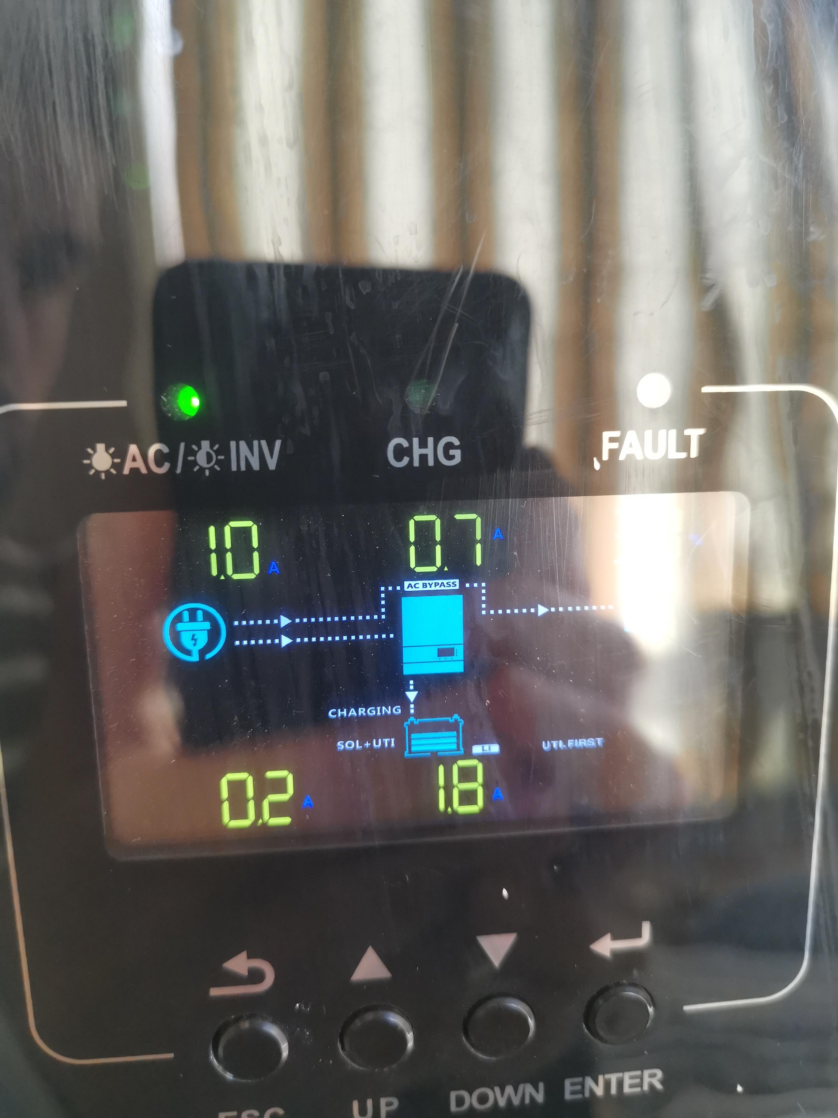
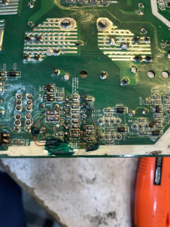
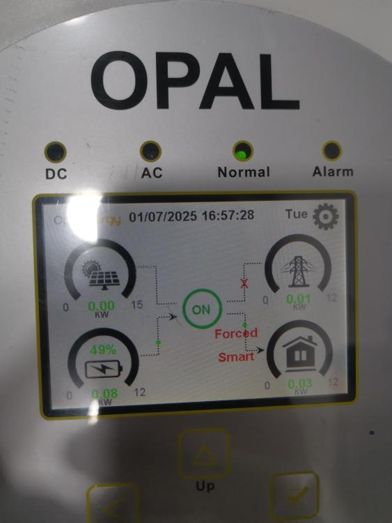
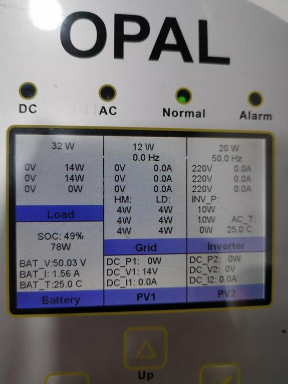
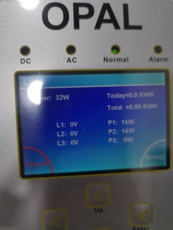
Hi, I received the above inverter, which is not running. I checked the IGBTs and found that some of them were broken. So, I replaced them and checked all the components around. The defected IGBTs were related to the Buck circuit. After assembly and running on, the inverter is showing normal operation. However, I tried to measure the output voltage, and found out that no Voltage there! I checked the configuration multiple times and did a factory reset, but the issue still persists. I attached the screenshots below for reference. If anyone could explain what's happening would be very helpful. Thanks
-
I decoupled the MPPT board and fed the UC3845 with 15V and the transformer with 135V and shortened the Opto-coupler, the noisy sound is there. I replaced the transformer and still same result. The PWM is around 5.4KHz with 50% duty cycle. I am still unable to find the issue
-
Thanks @Coulomb, Okay now I have a better vision on the board, still missing a point, which is the Ground related to the 15V feeding the Ground pin of UC3845 in the soft start circuit, from where is it coming? Cause the two wire coming from main board are +15V and +150V (Battery SPS output). Nevertheless, I am still encountering problem in the MPPT board for bootstrapping, let me explain what's happening: I starts the inverter, when the relay connected to the soft start circuit runs, the soft start transformer is making noisy sound, and after few seconds the inverter gives error 09. I measured during this bootstrapping the BUS voltage, it is increasing slowly till reaching only around 160V before the inverter stops and gives error 09. What probably is causing the problem? I changed almost all parts related to the soft start circuit!
-
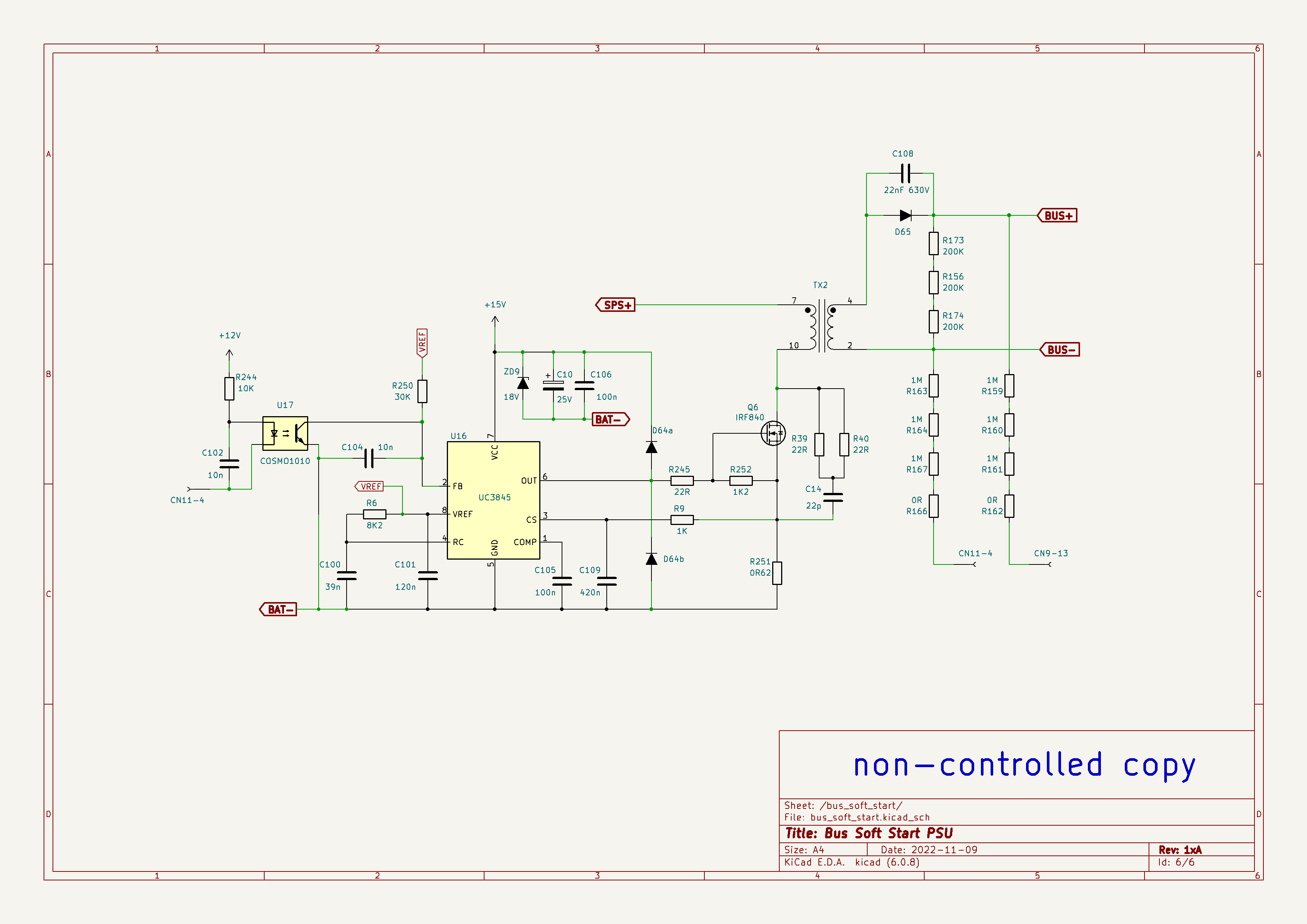
Hello folks, Can anyone explain the voltage source of +15V of UC3845 in the Bus soft circuit in the MPPT board VMII? I can see only the voltage 120V coming from the main board, then altered somehow in the cap C10 25V then feeding the UC3845 with +13V What's happening on my side it is about burning out the UC3845 and the double diode under it KL4 directly when turning on the inverter. SO I started researching on the circuit schematic and found out the above wonder scenario for me at least! Hope the experts here can help me on getting this more obvious Thanks

-
Here is a video describing the behavior I checked all regulators, SPS mosfet and driver and all are fine petal_20241014_155104.mp4
-
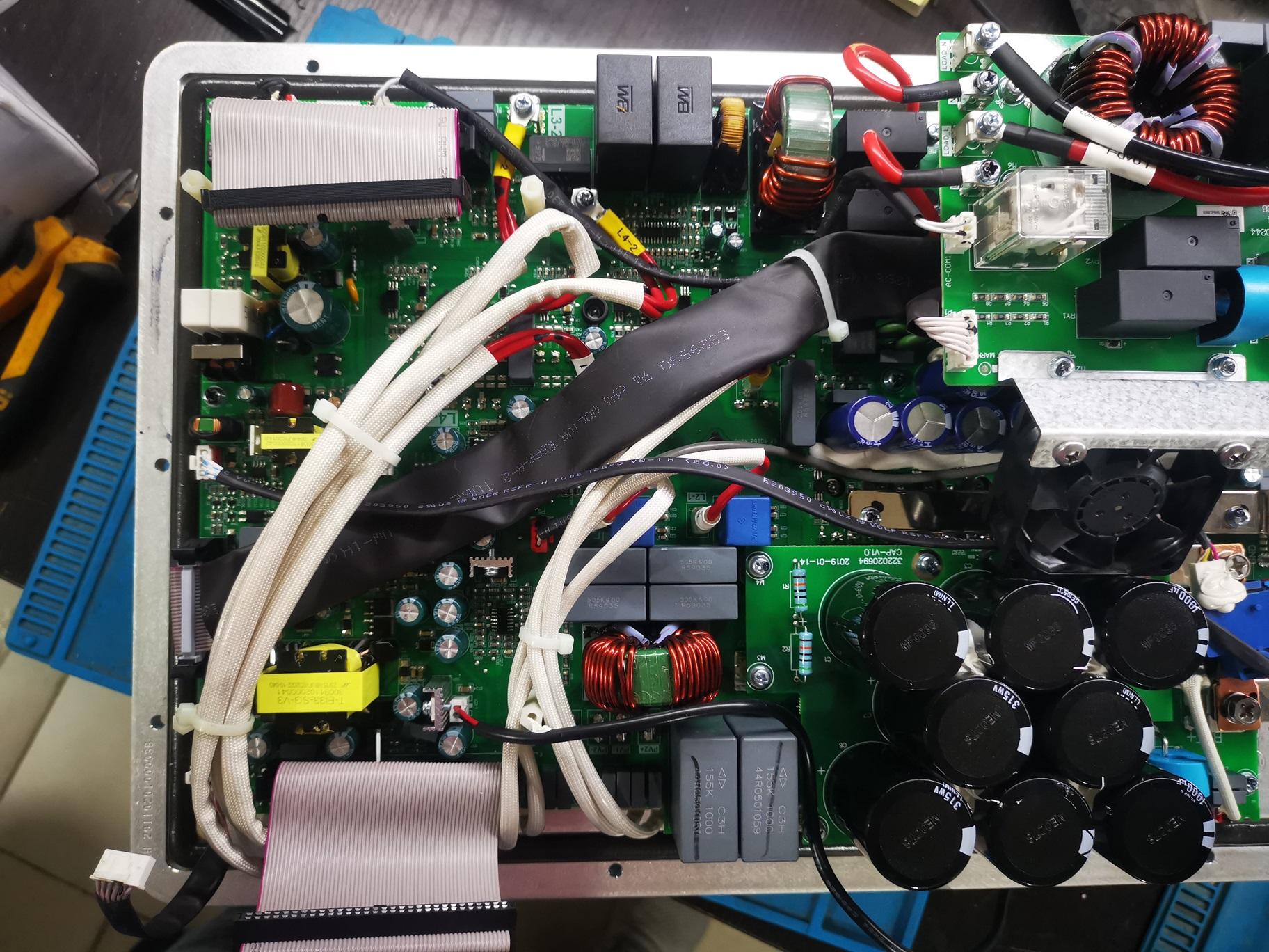
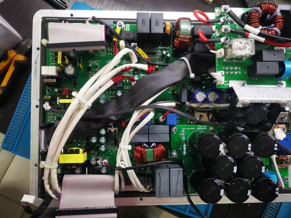
Hi, This is my first attempt to repair a DEYE inverter. I fed with 50V battery voltage and pressed the button ON, however it is not turning ON, and I noticed the LEDs on control board flashed for milliseconds periodically (it seems like failing to start). I found out some IGBTs are shorted out, so I had to replace them and their gate drivers. Now I have the startup issue only. Can anyone advise where to start to check the possible reason for this failure? You can find below the inverter board as a reference
-
Thanks @Coulomb for the amazing explanation
-
Thank you @Sidewinder 🌹
-
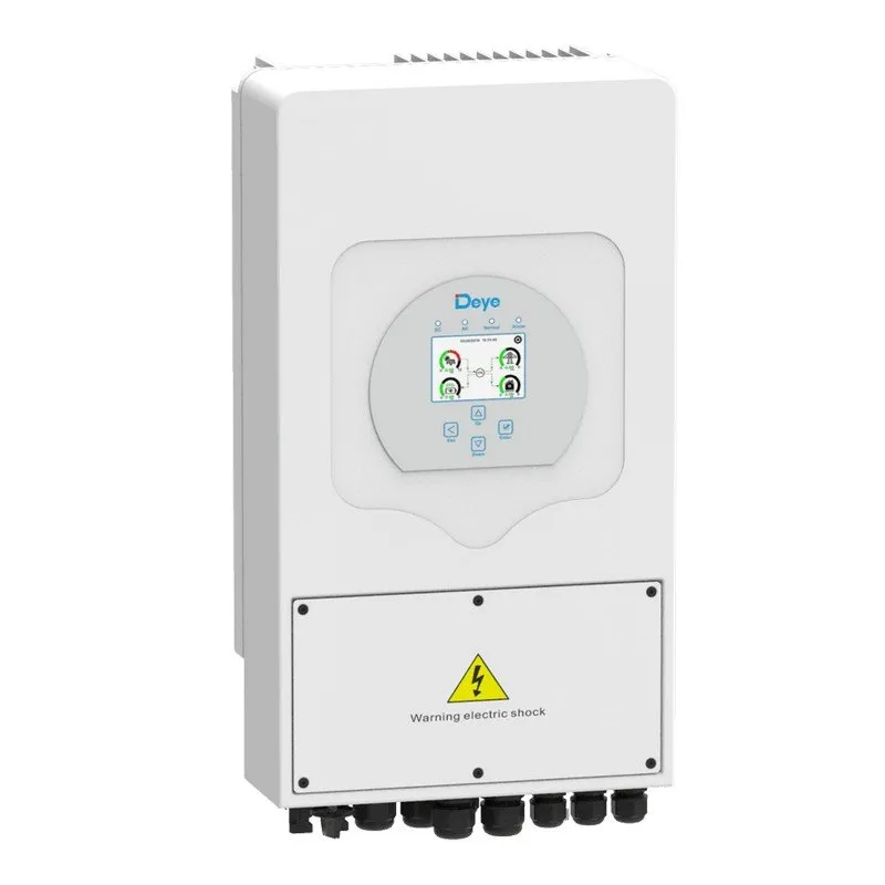
Hi folks, I just received a defective Deye 5Kw and this is my first time repairing such an inverter model. Kindly if anyone has the service manual for it, share it with me Your support is much appreciated
-
Hi folks, Recently I was wondering about the purpose of implementing the buck circuit in the middle between DC-DC and DC-AC circuits in solar inverter Can anyone describe it well? Thanks in advance