Adnano
Members
-
Joined
-
Last visited
Everything posted by Adnano
-
Yeah correct, the supply voltage is about 180V.
-
Hi folks, As diving into solar inverter circuit diagrams, I have just noticed a circuit that I didn't get its purpose use, which is the supply circuit for UC3845 in the main SPS in VMII inverters. I have attached a screenshot for reference (The part where exists the 2SC5353). I just wondered why we don't eliminate all the transistors and zener diodes and keep only the series 50K resistor. If anyone can explain the circuit would be highly appreciated. Best Regards

-
I measured the voltage between Shutdown pin and Ground(-12V) pin of 3525, it gives 1.2V, which means the shutdown pin is almost near to -12V pin, then the IC is in stop state! In other hand, the voltage between pin 2 of opto-coupler and -12V is 24V, which means the Shutdown is not activated from DSP!
-
Unfortunately I don't have another controller to test
-
Look, I found this video that is similar to my case. If u can notice, the voltage at Mosfet gate is about 7V when disconnecting all transistors
-
The problem is originally that pulses are not generated from the 3525. It only gives output when shorting the optocoupler and supplying it with an external 24V.
-
Actually I measured the signals directly on 3525
-
-
-
I supplied the IC with +12 and -12 v, it is producing signals perfectly. What is the next step? Thanks
-
Finally i have got this resolved, The issue was existing in the resistor between op amp output and negative input, having the value 7.5 kOhm Thanks everyone for the brilliant collaboration
-
The voltage between +Vc and -Vc is correct = 24V The output of phase A is a +12V which is causing the 530V I don't know the source of this voltage
-
Thanks @BritishRacingGreen for your detailed expalanation, much appreciated. So principally, I should look into - 12V regulator circuit (LM7912 and capacitors)
-
Guys there is no PV connected This is happening without applying solar voltage
-
Hello folks, I am facing an issue with a Growatt inverter which is making me crazy, it gives a fault code 61 (PV voltage is too high). THe LCD display shows a 530V PV voltage! I measured the two points of IC output marked on the image below, it says 11.6V. The issue exists when putting the MPPT board in place, so when disconnecting the NEGATIVE bus voltage, it is working without the problem. I have tried to remove all components each one to check if any causing this issue, with no success! I replaced the 330K resistors as well. First question, is the IC of voltage and current measurement is TL072? Second question, what do you think is causing such issue?

-
Do you mean keeping the optocoupler short will not affect the inverter functionality?
-
Thanks @Coulomb for your kind reply. I have tried to shorten the opto's output and I found out that pulses are generating. What is the next step?
-
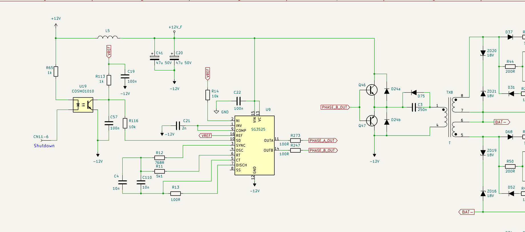
Hello folks, I have an 3KW 24V inverter having fault code 57. I removed all transistors and test all drivers. Output, buck and PV IGBT have correct voltage values, when measuring the voltage between Source and Gate (5V) while the IGBT removed. But the voltage across battery Mosfets and Charge IGBT is 0V. I replaced the SG3525 and still same issue. I checked all measure around 3525 all correct. What do you think the 0V issue is coming from? Maybe from controller? The schematic reference I referred to during my investigation is And here is the inverter


-
I didn't found any justification for the values and I removed all components and replace them, and same result. It seems it is designed like that!
-
I just run the inverter with the existing behavior and it seems it is working normally (charging and discharging)
-
Hi folks, As mentioned in the title, can anyone help me find the service manual for this kind of inverter? I really appreciate any help you can provide.

-
I have checked the service manual of VMII and found out that the transistors are both PNP and the value between B and C pins is normal and should be 0.063V which is my case as well!

-
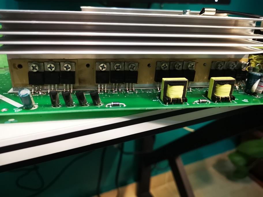
The part I am talking about differs from the one you are meaning. I am talking about the circuit after the small transformers as below

-
I didn't do anything, just turned the inverter on. No, I didn't replace them as they are good (I removed them all and the short still exists. How come the SG3525 can affect these transistors? As both circuits are isolated from each other by transformers! Yeah it is around 21Ω There is no short on SG3525 pins
-
Hi folks, I am suffering from a damaged Voltronic inverter having its Mosfet battery blown, I have replaced them all and I noticed the 10R resistors of Mosfets drivers are blown as well so I replaced them. I am struggling with the 2SA1020 transistors value between Base and Collector, which indicates around 0.038V when using Diode mode. I have suppressed these wrong values and tested it, it is working and outputs 230V but it is draining around 2.6 Amps with no Load, which is a weird consumption (usually it is about 1.6 Amps). Please take a look at the screenshots attached for more details. Can anyone have an idea why the PNP transistors are shortening? Knowing that all parts' values around are good. Thanks