


zennomind
Members
-
Joined
-
Last visited
-
It appears that all it needed was to restart the inverter. I can now feed energy from my MG4 (or my second PV system) into the house batteries.
-
16A AC line is visible (220V and 50Hz) on the inverter but there is no battery charging happening. PV charges the Pylontec batteries (14KWh stack). I have DC isolated the PV expecting the AC line to charge the batteries but it isn't. I don't need the AC line in to power the load, it just needs to charge the batteries. Do you have any ideas on what the issue(s) might be? Voltronic inverter settings are: 16) Charger source priority SNU (solar and utility) 100) Timers for SNU are 00:00 (I assume that this is always charging since PV is charging the battery.) 2) Max charging amps is 60A (I'm only using a 16A line in running at 220V and 50Hz and the solar amps are low. I know the V and Hz because that's what the inverter is displaying.) 3) Input voltage range is APL (90 - 280VAC) 11) Max utility charging amps is set to 30A
-
Also, of interest and potentially helpful to someone else. The issue I mentioned in the first post with high voltage and low amperage from the panels being reported by the inverter was due to a failing battery in the stack. I think that this accounts for some of the high voltage issue i.e. where there was no variation in the amperage the voltage remained high. Since I removed the battery from the stack charging has improved by the inverter being able to allow the amps to increase and dropping the voltage. I can't say that under open circuit conditions the incoming voltage is lower because as a cold wind blew over the panels I could see a voltage increase and so with the variability it's not possible for me to draw conclusions. The only conclusion I can draw from removing the battery is that the voltage and amperage is now more variable and this means that at least during charging the voltage can drop allowing more watts to flow due to the higher amps. I know that the words I'm using are not necessarily related to the reality of electricity and are the words a lay person would use given a general understanding of how a system like this works.
-
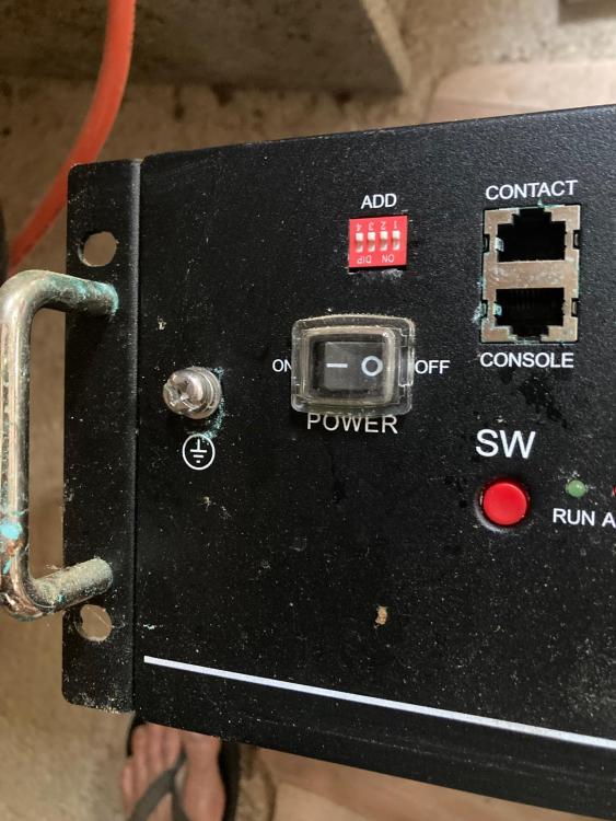
@GMAC thanks for the useful tip about removing the suspect battery. After 20 something years working in software and often removing sections of code to see how the overall system changed that's something I should have considered. This says something about our ability to think laterally. Anyway, I removed this battery and the charging remained constricted. I removed battery 3 next, rebooted the inverter and the charging returned to what it should be i.e. not stuck on high voltage and low amps. So I charged the master and one slave to full capacity. Then I reattached batteries 3 and 4. Turned them back on and left them for a few minutes as there was some movement of charge between the fully charged and the last two batteries that were on about 40%. After that I turned the inverter on and the DC isolator. Surprisingly, the charging returned to normal! But the battery 4 charging light stuck at around 75% charge and so I switched the system off. I'll get the battery replaced. Dip switches: The master battery has 1000 for CAN communication with the Axpert IV inverter. The other three batteries are all on 0000 as shown in the photo. Both of my systems have been running with these settings for 2 years.
-
 Coulomb reacted to a post in a topic:
Over voltage problem with Voltronic Axpert IV (5600W) inverter
Coulomb reacted to a post in a topic:
Over voltage problem with Voltronic Axpert IV (5600W) inverter
-
I assume that there is a problem with our Pylontech battery stack. There are no error messages on the inverter and the BMS has not thrown any error messages via the red light on the batteries. According to the Axpert IV inverter the string is pushing 400V at 1A and it is not varying much around those parameters. Here is some background to this system. I have two sets of panels (3.3 on the ground and 3.8Kwp on the roof) each connected to an Axpert IV and 4 x 3.5Kwh Pylontech stacks (labelled Turbo Energy and US3000C respectively). The roof system has always varied the voltage more than the amperage and the ground has varied both the voltage and the amperage. I swapped the inverter, the solar panels and all of the cables to see if the charging amperage could be changed. The charging remained as I described in the first paragraph. Additionally, both sets of panels, inverters and cables work as well as each other on the ground PV Pylontech battery stack. So I assume that there is a battery stack issue. In the roof mounted stack one battery has some corrosion around the earth terminal and in the communications ports which, to me, indicates a chemical leak, however, the voltages on each battery are the same (49.4V) and, as a lay person, I would imagine that that battery might not be charging as well as the other ones in the stack if there was a leak. I've attached an image of the corrosion. I don't have any hardware or software for reading the internal Pylontech states and I run Linux not Windows. I also don't have a LAN. So anything requiring Windows or a LAN are a non starter. Would the BMS be throttling the charging? Is there anything that can be done to get the battery charging properly?

-
Thanks for the last three messages/thoughts. I had not been notified that you'd posted. @P1000 I could have bought a Solis hybrid for a good price but the Axpert IV is still working and so I decided to remove a panel from the string. I left the system off until a few days ago and just used my second set of panels, inverter and battery bank. I got up onto the roof and removed the last panel from the string. So that drops the Voc from 455 to 417. So correcting for ambient temperature changes would put this string at just below 500V at around -21C. We only drop to around -5C on a few days a year and that's generally early morning temperatures and so this should eliminate any over voltage. The string output is also more healthy now.
-
Thanks @Coulomb I had figured out my mistake just after I posted my thought about the circuit breaker. What about the idea of putting in a SPD that I mentioned on March 12? This would just be to catch the rare event where the 3 variables occur to cause the over voltage.
-
I misunderstood the term "overload protection". In fact I thought about it in relation to AC circuit breakers and realised that the voltage variance is not what causes the breaker to trip. I already have 1000Vdc surge protectors against lightning strikes and so my follow up thought after the circuit breaker thought, is why not put a resetable 500Vdc surge protector between the isolator and the inverter. Perhaps, something like the following: https://www.aliexpress.com/item/32847385291.html
-
It just occurred to me that I could put one of these 500V DC circuit breakers between the isolator and the inverter: https://www.amazon.fr/dp/B097PFSDQV/ref=sspa_dk_detail_2?pd_rd_i=B097PFSDQV&pd_rd_w=jFVCh&content-id=amzn1.sym.2b631440-6276-45ab-a2e4-50e8867cfe1d&pf_rd_p=2b631440-6276-45ab-a2e4-50e8867cfe1d&pf_rd_r=2SBBMHRHSAKYCGN0N7QE&pd_rd_wg=ylk6g&pd_rd_r=3d0a7c95-f10d-4145-ad8b-1f76fba56d6a&s=industrial&sp_csd=d2lkZ2V0TmFtZT1zcF9kZXRhaWwy&th=1 This would protect the inverter in the cases when all 3 variables that could cause an overload have the potential to occur. Given that so far this is a very rare case and that I have stated that getting up on the roof and changing the configuration is highly problematic for me at this time, this seems like a good solution.
-
@P1000 do you have any ideas when it comes to off grid inverters that can handle 600V?
-
zennomind reacted to a post in a topic:
Over voltage problem with Voltronic Axpert IV (5600W) inverter
-
@TaliaB, thanks for your input and concern. Maybe I wasn't as clear as I could have been. I had to turn the DC isolator to the "off" position in order to remove the face and check the voltage from the panels i.e. there was no load on the panels. I had wanted to check the voltage on my multimeter against the voltage displayed by the inverter but was unable to do that via probing the isolator connections while the inverter was under load. You might have read some of my other comments above where I have stated various things about this array e.g. that it has been running in situ for a number of years before I bought this place and I've been here almost 3 years without an over voltage fault. I also stated that this Axpert IV inverter has an over voltage protection built into it. The inverter is working (charging the battery) within the upper 450V range even when there is no load and as I stated in my last comment I let the battery get fully charged with the inverter under no load and the voltage was under 450Voc.
-
I couldn't get the front of the DC isolator off when there was still power going to the inverter. So, I took the face off when I cut the panel supply to the inverter and measured the Voc as around 484V! Considering the ground mounted array that I installed, that is a lot more than I would have thought it would be. My multimeter only runs to 500V DC and so I was not that keen to keep measuring. I let the battery fully charge without a load and there was no over voltage fault. It was later in the day and the panels were probably warmer than the previous time when the over voltage fault was recorded. Unless anyone has other ideas I'm going to have to conclude that under the 3 conditions of battery fully charged, no load on the inverter and low panel temperatures there can be a situation where the voltage goes over 500V. Changing the array to 2 sets in parallel is a major undertaking of removing all of the roof tiles as I can't put any weight on them, rearranging the rails, sealing the old roof holes, rewiring etc.... So, I think that I'll just have to manually manage the system when there's a possibility of the 3 variables occurring. Thanks for you help and educating me on how a system like this works.
-
Thanks @Coulomb I always appreciate knowing how things operate as well as getting to the bottom of errors. You've given some good descriptions, I can picture what's happening. I spent many years at UND in the late 80s and early 90s but not having had a background in electronics makes working things out a bit tricky. The PV input area on the LCD is blank when it's showing the over voltage error so that's why I described it as switching off the PV input. I'm not sure what the upper DC limit is on my multimeter, it's not something that I've ever had to use. I'll have a look tomorrow. I could probably remove the face of the DC isolator to read the voltage while it's still being sent to the inverter. I don't want to push the probes into the inverter as the space is too narrow. I may only get around to this later on Friday or on Saturday as I've got some horse shit shoveling to do. That's not a euphemism 🙂
-
@Scorp007 As I said the inverter does cut the PV input. It seems to have both over voltage and short circuit protection as stated on this seller's site: https://tienda-solar.es/en/inverters/1033-solar-inverter-charger-axpert-vm-iv-5600-48v We all know that we can trust what we read on the internet ;-D
-
@Skyelmad and @Chris Louw here are the specs from the Axpert booklet that came with the Axpert IV. I only installed the array on the ground and not the one on the roof and so I don't know the panel voltages but going with what's normal for that size I assume that the open circuit voltages are within the 500Vdc cut off. @Skyelmad I agree with your diagnosis, the low temperatures at the moment are probably sending the voltage over 500Vdc. I assume (I can't see anything about this in the manual) that my Axpert does have over voltage protection as the PV array gets cut off.


