JO+e
Members
-
Joined
-
Last visited
Everything posted by JO+e
-
Hey Tim, glad it helped 🙂 I recently set up a Pi Zero 2W with a Waveshare board for a trolley type backup system and actually found that there is a utility that can do the whole setup for you - I followed some other guide for the Pi and struggled getting comms to the battery until I can across the shell script which sorted things out. If I remember, I'll go looking for it again and post a link to it here which might be helpful to any future attempts.
-
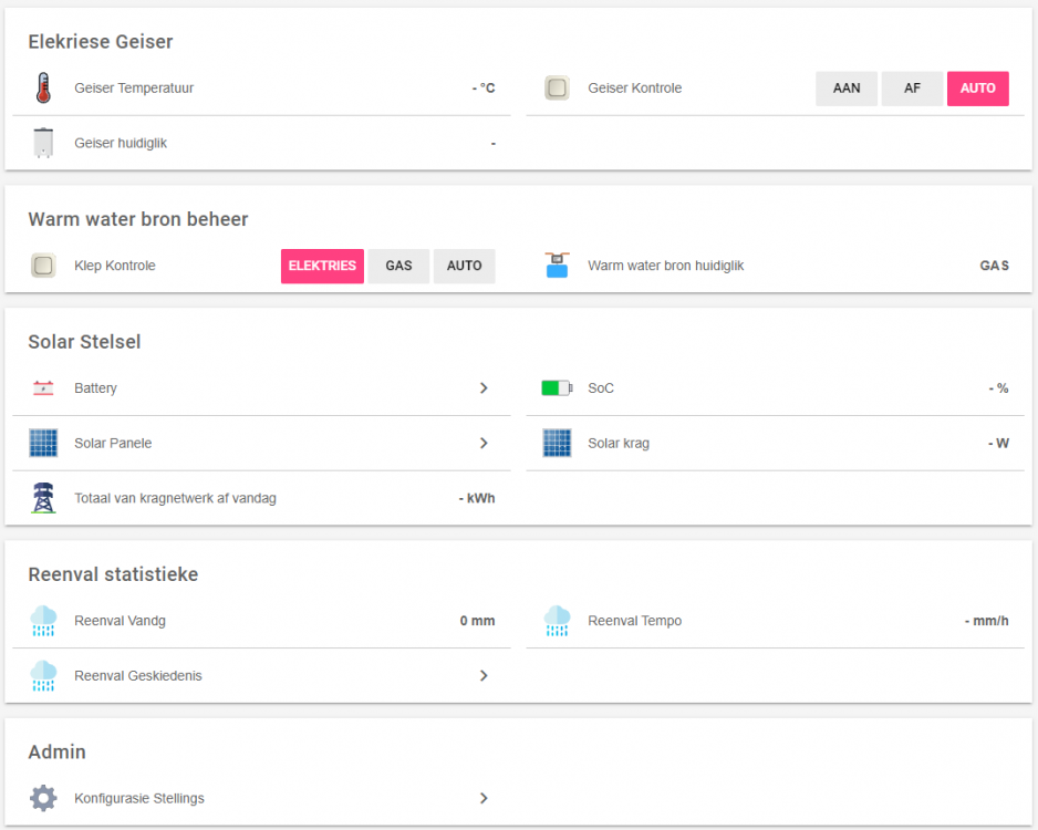
@Supergeek woops, my bad. Sorry, completely missed your question. In my case I didn't get too fancy (not my system). The metrics from the inverter are basically just used to control a geyser automation system. My father-in-law basically runs off-grid, so I use battery % and PV yield to dump excess energy into their electric geyser during the day and also ensure that the electric geyser doesn't deplete the batteries when there's limited PV available. And then I also display some basic stats via openhab (no graphing, father-in-law is happy with the info from the luxpower app, plus I'm not sure the Pi zero would be happy with running grafana or similar). For the rest of the system I monitor the electric geyser temp (DS18B20 + Tasmotized Sonoff TH16 with a retrofitted 2kW geyser element, keeping the original thermostat in place), which then determines the hot water source between the electric geyser and gas geyser via an electrically actuated 3 way valve (+ another Tasmotized Sonoff and a SPDT relay) and some configurable temperature thresholds in the OH app/interface. Quite a basic little setup, but it works nicely 🙃 Not very flashy, but this is the basic (OH) interface (this is just the template on my machine, so no values, as I'm too lazy to try log into the OH account at the moment) - the rain stats are shared from my system via a cloud MQTT broker - the older you get, the more you care about rainfall stats 😆 (they're hijacked from an Oregon Scientific kit using an RTL Software Defined Radio setup and pulled into my system): I might do something similar (water source control) in my system once I (finally) get done installing the gas geyser.
-
Hi Rid00, Not sure if you've come right, but I'm busy toying with this exact situation (for my father-in-law). You can have a look at GitHub - celsworth/lxp-bridge: A bridge to MQTT for communications with the LuxPower range of inverters. So far I've managed to get it running on a Pi Zero W 2 and was able to retrieve info from the inverter and publish via MQTT during a quick test over the weekend. I haven't set up anything with the automation (via OpenHab) yet (in progress) so I can't yet comment beyond that, but so far it looks pretty promising. You can have a look at the list of pulled and published metrics here lxp-bridge/inputs.md at master · celsworth/lxp-bridge · GitHub. Seems you can also issue some commands at present, but for my current use-case I'm not really interested in that (yet, anyway). Happy to field more questions if you get stuck. I should be in a much better position after commissioning the little system over the weekend and then keeping an eye on what it's up to. Cheers Joe
-
Hi all, I'm having a bit of an issue with my setup and I'm not quite sure whether it's normal. I started with a 3kVA/3kWp system and have been slowly upgrading (now 5kVA/5.4kWp). When I fitted the new inverter over December I noticed that some of the wires near the PV combiner were getting uncomfortably hot, and the bigger inverter was just making things much, much worse. Most of the heat was coming from the 22x58 fuse between the (Victron) MPPT/Charge Controller and the batteries, but almost everything in the combiner box was heating up badly. What I've done so far is: replace the 22x58 fuse holder & fuse (Onesto -> Inge) rewire everything after the 10x38 PV string fuses. 16mm2 (was originally 6mm2) cable for the combined PV (carries < 40A at max load), and 35mm2 (was originally 2x6mm2) cable between the MPPT and battery (+ve goes through the 22x58 fuse that heats up - current is around 70A at max) Tighten/retighten all the connections (bare wire, no lugs) Measure voltage drop over the various components From my measurements (see 4 above) it looks like the MPPT-Battery fuse is dissipating around 6W, which from looking around seems to be about normal (e.g. Victron 125A/58V mega fuse lists voltage drop of 90mV, which at 70A would also give roughly 6W dissipation). I guess because of poor ventilation in the combiner box heat buildup is to be expected, but it "feels" like something isn't quite right with how hot the cables and fuse holder get. I just don't really have any practical experience with DC stuff like this to know whether it's to be expected or if I should keep looking for another possible cause/problem with the setup. Can anyone maybe offer some guidance? Should the fuse holder really be getting that hot, or does it sound like there's still a problem somewhere and if so, what should I be looking for? Thanks for any input
-
Cool, thank you! Hopefully some further poking will help resolve my concern. I wasn't even aware of the defect that affected the 5kVAs, so it was more of a general question regarding anything that could potentially lead to overheating. I know it has an internal fan that sounded a little iffy to me since I got it, but it didn't sound really broken (and does still spin). Sorry for the stupid question about the cover. As mentioned previously, I didn't perform the installation and thought it was just the black panel at the bottom that comes off for all the wiring/VE.Bus etc. I just have a routed ethernet cable I fiddle with occasionally Let's see if I can get around to getting a sonoff set up with a temp probe over the weekend and see what it's getting up to
-
Mr @plonkster, following some further testing I think your assessment is correct as it's doing the same thing in the current configuration. Yesterday: Today: Ambient got to around 37 C yesterday (no additional cooling) and 35 C today (with a fan blowing directly towards the inverter, but with the cover on). So now I'm not quite sure where to from here (I don't want to void the warranty, but was thinking of removing the cover and testing with the fan again - maybe measuring the heatsink temperature with a DS18B20), but it's got me wondering: Is this expected? Should the inverter really be overheating/derating at 35C ambient, or is it possible there might be something wrong with the inverter? My personal feeling is that this shouldn't be the case, but I'm also hardly an expert. From our earlier discourse I'm assuming an alarm/notification isn't to be expected under this condition? If there might be something wrong with the inverter I'd like to confirm it before contacting the retailer. Any further guidance would be greatly appreciated.

-
Cool, thank you. Always eager to learn a bit more about how things work. Quite possible, yeah. As mentioned, I'll keep it in this configuration for a while and see how it behaves. Additionally, I've moved one of my Z-Wave temperature sensors into the cupboard to log the ambient temperature and see whether there's any correlation (crude as it may be) to throttling. Is there any way to monitor how much power the inverter is supplying (from DC) in VRM or otherwise? I noticed yesterday that the PV Charger (Venus) would report more than 2.4 kW at times, and it's a bit difficult seeing what the inverter is actually doing (AC loads + Critical loads - Grid =? PV Charger - I'm aware there will be some losses though) I'll report back once I have any further detail from the testing. I do however suspect that there might be an issue with the configuration of my system as several of the charger settings were not according to the parameter values detailed in the Victron reference info (I didn't install/commission/configure the system initially), but let's first see about confirming or ruling out the temperature component. Thanks again for all the assistance, and your patience with me 😉
-
So rather than try additional cooling I opted to try something else that previously didn't work i.e. set the ESS mode to "Keep batteries charged" (previously with the grid feed not working it would limit the PV power to whatever load was present without feeding anything to the grid) and observe the behaviour in Venus. Although today was around 2-3 C cooler than yesterday I didn't note any throttling of the MPPT. The overall yield for the day was roughly the same (1% less) as yesterday (with the throttling), but I think it was a bit more cloudy today as well. I will keep it set like this for the next few days and see if I notice any throttling, but so far it doesn't seem to be related to temperature. Just for my benefit, I'm not really sure of what the Multi looks like inside, but I'm assuming the temperature you're referring to (and associated heatsinks) would be for the FETs? Lastly, I did note that the reported battery voltage was a lot more stable in this configuration, staying roughly at 52.3 V the whole time in contrast to jumping above 53 V as observed yesterday.
-
Such a good explanation, even a simpleton like me can follow, thank you! How do I go about confirming whether the Multi is running hot? It's physically hot to the touch, but is there any way to retrieve temperature readings from it - I'd prefer empirical data to my anecdotal observation (MQTT, console, etc?). It isn't exactly installed in the most ventilated or coolest spot in the house - it's in the passage cupboard where the geyser used to be installed, so quite a lot of space, but like I said, very little ventilation. For perspective, the passage ambient temp is currently sitting at 32 C, so it's a lot warmer than that in the cupboard itself. I could quite easily move one of the temperature sensors I have into the cupboard, but again, that's just going to give ambient so I'm not sure how useful that will be. Or do you maybe suggest running a test with additional cooling to confirm whether it's derating as a result of temperature?
-
Sorry, the reason I'm fixated on absorption is that there is a correlation between the behaviour (limiting to 1.8/1.9 kW) and the amber LED on the charge controller, indicating absorption, so as far as I can tell something on the charge controller is causing the behaviour. /Hub/ChargeVoltage indicates 52.4 V. The MPPT charge voltage is however indicated as 53 V (I'm guessing this is the 0.6 V offset?). I also considered temperature at some point, but figured that would be a more linear degradation (I guess I was wrong), and also without the correlation to the charge state that I've noted. Is there anywhere I could confirm the temperature or derating? I've never seen a temperature alarm, but I'm also not sure if this would be expected.
-
Thanks @plonkster. I literally just increased the offset as suggested, checked Venus and a few seconds later saw how the battery jumped from 93% (53.something V indicated in Venus - it was however in absorption, so something with the display is iffy) to 100% and the yield throttled from 2600W to 1900W =/ I checked and the amber absorption LED on the MPPT (150/100) is lit, so ? I really don't think the cable voltage drops are the issue, but I can try measure these. I'm assuming there is a LOT of debug info available if you know what you're doing (sadly I don't), but if I know where to look I might be able to make more sense of it, so if you have any other pointers I'd be very grateful. Edit: Thanks to some cloud the battery discharged a little and it's back up to 2.6 - 2.8 kW. Amber LED off. When it was limiting though, I noted that it was pulling around 200 W from grid with the setpoint at 0 W. And as I'm typing this it's back to 1.9 kW (battery voltage indicated as 53.4 V in VRM).
-
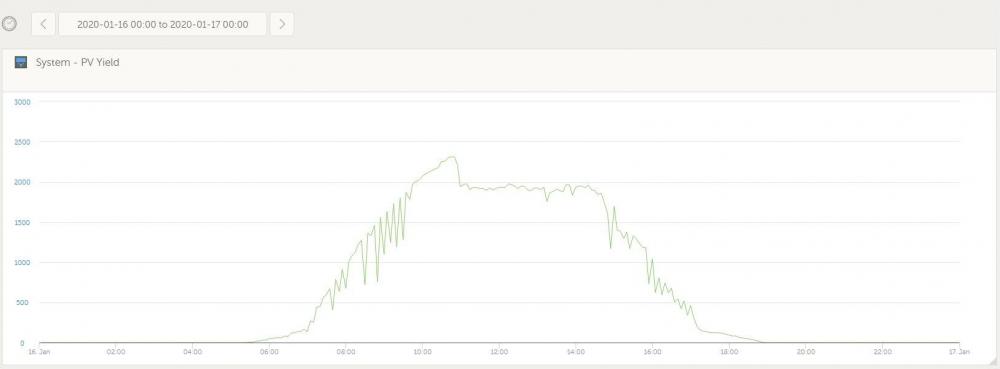
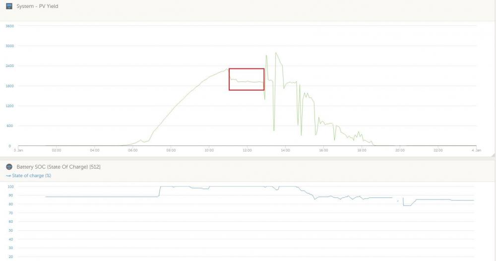
My apologies for the extremely late feedback, but it took me some time to get around to doing some proper investigation. So it would seem there were possibly two issues originally. SVS and then later Venus fw 2.40 (SVS disabled) seem to have fixed the one issue where grid feed was not working as expected, but what I soon realised was at some point the MPPT charge controller would start throttling when the batteries reach 100% charge. Subsequently I updated the firmware on the MPPT (v1.46) and Inverter (467), installed an additional battery (Pylontech US3000), set up the ESS assistant again and still the same result. What I have noticed is that there appears to be something wonky with ESS and the MPPT. The bulk LED on the charge controller does not flicker as indicated in the documentation I saw (which is supposed to indicate external control), but does show ESS under state in VictronConnect and shows external control in Venus. The second oddity is that Venus (and the inverter) will show that the battery is in the absorption charge phase when everything works fine (i.e. battery at or near 100%, grid feed working), but at some point the amber absorption led indicator on the MPPT charge controller comes on and that's when the limiting occurs (solar yield limits to ~1900W). I don't understand why these indications aren't in sync between the MPPT and Inverter, or if this behaviour is expected, but it seems rather strange to me, and results in unexpected behaviour. I did however read that the MPPT switches to constant voltage mode when in absorption, so I'm not sure if this is part of the cause. I would have expected that the charge controller LEDs would continue to show external control? Here's an illustration of what I'm seeing: Each time I've gone to check on the system when the yield drops to ~1900W I've found the absorption LED lit on the charge controller. Unfortunately VRM only lists external control for the MPPT state so I can't show the correlation in the image (the behaviour after the highlighted time period coincides with the MPPT leaving absorption, clouds, and partial shading from about 3PM so don't worry too much about that). Any thoughts? Is this behaviour expected, or does it seem like something may not be working as expected? Any and all input would be greatly appreciated!
-
Thanks @plonkster! Running v2.33 but will give v2.40 a bash tomorrow night (unfortunately the updates wipe my manual tinkering to get the Pylontech and RS485 HAT to work, so not going to tackle that now) and report back. I've also just enabled SVS and will see how that fares tomorrow - it really helps knowing how this all works together, so your brief but insightful explanation is truly appreciated. Thanks for the super quick assistance!
-
Hi all, I have a little issue that I haven't quite managed to figure out. It isn't really my intention to feed to the grid, however the fact that it doesn't seem to be working when I've enabled it (as far as my limited understand goes anyway) is bugging me, so I'm hoping somebody can point out what I may be doing wrong. I have a Victron Multiplus-II 48/3000/35-32 with a system pretty much like this: Victron Grid-tied setup from scratch I have ESS set up and working (Venus OS on a Raspberry Pi), but I originally noticed that the MPTT was being throttled as soon as the battery was (almost) fully charged. This was confirmed by adding additional load and observing the solar yield reported on the Venus UI (which increases in response to additional load). The ESS page notes as follows: But even with "Feed-in excess solar charger power" enabled in the ESS settings I rarely see any grid feed. It almost seems like the grid set-point overrides grid-feed. I've fiddled with a lot of settings (Venus only) and went through the ESS manuals briefly some time ago but haven't managed to find anything that works. I'm definitely a novice with the Victron stuff, so hopefully somebody can give me some pointers, or tell me what other information is required (at the moment I'm not sure what to provide to assist). Running Venus firmware v2.33 on the Pi (think I've tried 2 or 3 different versions since the install) Multiplus reports firmware version 453. Any help/input will be appreciated.
-
Well, I for one am extremely grateful for your efforts porting it to the Pi, and you did a great job with it - the system has been rock solid since July. Having had everything else in my system installed for me, it's the one piece of the install I can take a little pride in 😁 I just need to still figure out why the system appears to throttle feed-in 🙄 Absolutely no idea whether the waveshare HAT has galvanic isolation (unfortunately I only have a very basic grasp of electronics, but I don't see anything that looks like an optocoupler on the board), but I've got it powered from mains (on the essentials output side). The TI looks interesting, but I really just went with what I could find that looked like I'd be able to hack to work, which I did (thankfully). Thanks for the bit of advice when I bothered you via PM as well!
-
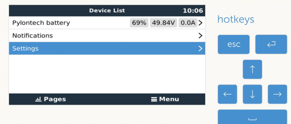
Hi all, So I decided to be “clever” and try get a Venus Pi running instead of a GX device as part of my upcoming solar installation. I expected the integration with the Pylontech battery to give me the most headache and wasn’t far off, so I figured I’d document what I did to get it running here in case it helps anyone in future. Hardware/Software: • Raspberry Pi 3B+ • Waveshare RS485 CAN HAT (https://www.robotics.org.za/W14882?search=wave%20rs485) • Venus OS Firmware version 2.23 A bit about the CAN HAT: I saw here (https://github.com/victronenergy/venus/wiki/RaspberryPi-CAN-Interfaces) that the MCP2515 chip was supported in the Venus image, although this specific HAT wasn’t documented – I just figured I could hack it to work. OK, on to the instructions (Disclaimer: I don’t really know what I’m doing, and relied heavily on information from other similar threads e.g. https://groups.google.com/forum/#!topic/victron-dev-venus/C4-3JhHpbcY). The guide assumes you’re familiar with SSH and have access to the terminal via PuTTy (Windows) or similar. 1. Add the following text to /u-boot/config.txt [all] dtparam=spi=on dtoverlay=mcp2515-can0,oscillator=8000000,interrupt=25,spimaxfrequency=1000000 2. Create /data/rcS.local and add the following text to bring the CAN interface up ip link set can0 up type can bitrate 500000 2 a) You can then check the interface with the following command to make sure it’s up and running: Ifconfig can0 can0 Link encap:UNSPEC HWaddr 00-00-00-00-00-00-00-00-00-00-00-00-00-00-00-00 UP RUNNING NOARP MTU:16 Metric:1 RX packets:0 errors:0 dropped:0 overruns:0 frame:0 TX packets:0 errors:0 dropped:0 overruns:0 carrier:0 collisions:0 txqueuelen:10 RX bytes:0 (0.0 TX bytes:0 (0.0 If the battery is connected and powered on, you should see numbers for RX packets (including some dropped packets which seems to only happen initially – my battery was not connected when I ran ifconfig hence all 0’s). 2 b) You can also verify communication from the battery using candump can0, which should return something as follows: can0 359 [7] 00 00 00 00 01 50 4E can0 351 [6] 14 02 72 01 72 01 can0 355 [4] 45 00 64 00 can0 356 [6] 80 13 00 00 D5 00 can0 35C [2] C0 00 can0 35E [8] 50 59 4C 4F 4E 20 20 20 can0 359 [7] 00 00 00 00 01 50 4E can0 351 [6] 14 02 72 01 72 01 can0 355 [4] 45 00 64 00 can0 356 [6] 80 13 00 00 D5 00 3. Then there is some fiddling to make the CAN interface visible to the Venus software (i.e. show up in the services menu). First create the following missing symlinks (each one is a separate command): ln -s /opt/victronenergy/can-bus-bms/service /service/can-bus-bms.can0 ln -s /opt/victronenergy/dbus-motordrive/service /service/dbus-motordrive.can0 ln -s /opt/victronenergy/dbus-valence/service /service/dbus-valence.can0 ln -s /opt/victronenergy/vecan-dbus/service /service/vecan-dbus.can0 ln -s /opt/victronenergy/mqtt-n2k/service /service/mqtt-n2k.can0 Note that all symlinks must be added – I initially got stuck as I only added the BMS which caused gui/ssh instability. Then you need to make Venus aware of the CAN interface by executing the following command, which creates the file canbus_ports with a link to the can0 interface: echo "can0" > /etc/venus/canbus_ports At this point it should have worked (after step 4), but I still had no joy getting the battery to show up in the Venus UI. Eventually I replaced “DEV” with “can0” in the following script file: /opt/victronenergy/can-bus-bms/service/run #!/bin/sh exec 2>&1 exec softlimit -d 100000000 -s 1000000 -a 100000000 /opt/victronenergy/can-bus-bms/can-bus-bms --log-before 25 --log-after 25 -vv -c socketcan:DEV –banner 4. Reboot Follow the steps in Section 5 of https://www.victronenergy.com/live/battery_compatibility:pylontech_phantom Reboot (not 100% sure if this is necessary – I’m compiling this guide from memory, and I had many, many detours along the way), and with a bit of luck, the battery should pop up in Venus, like so: Extra: During the troubleshooting I used the following command to test. Running it from the console immediately (within 2s or so) brings up the battery in the Venus UI. Killing the command results in the battery showing as “Disconnected”. This is why it’s necessary getting Venus aware of the interface and getting the service running automatically (step 3): /opt/victronenergy/can-bus-bms/can-bus-bms -c socketcan:can0 --banner --log-before 25 --log-after 25 -vv Hopefully I didn’t mess up the order too badly or omit any steps. As mentioned, this took me a little while to figure out and I’m doing this from memory which is admittedly shoddy at the best of times, so please forgive any obvious errors. Note that firmware upgrades wipe some of the modifications made above (I think maybe the symlinks but definately the changes to /opt/victronenergy/can-bus-bms/service/run (Step 3)) so just be aware of that. Questions or comments welcomed, and hopefully this helps someone in future.