Ironman
Members
-
Joined
-
Last visited
Everything posted by Ironman
-
-
Correct. 4 X US3000 = 14kWH. I also looked at Revov, but their BMS was not ready and they could not give me a timeframe for when it would be. And I got the Pylons for slightly more than the Revov's price per kWH. Bargain.
-
🙂 I don't know the details of the design - just trying to show that there would be a lot of heat generated if there is a voltage drop across the screw. I also know that - with HW Rev 4, when delivering 4500 Watt, the average current draw for the batteries are 102 Amp, at 4950 Watt. So there are about 450 Watt lost due to the inversion inefficiency. And thus, that at 4000W, the current drawn from the battery is likely to be about 102*4000/4500 = 90 Amp. Rough figures. None of these measurements are very accurate - but I think it is would be less than 140 Amp.
-
Disclaimer - I switched on the Multiplus while its case was opened. This is dangerous since there are high voltages and currents all over the place. On this forum, we are all interested in power, but power can be dangerous. Do not do this unless you know what you are doing. If you open the box - at your own risk - do not touch anything inside. The unit could be receiving AC power even when switched off. This is the problem with the Hardware Revision 3 unit: The one screw that has to transfer all the current to the low voltage side of the transformer is not capable of carrying the current. It glows red hot when drawing about 2000 Watt: WhatsApp Video 2019-10-27 at 18.51.07.mp4 You can also see the glowing screw through the air vents at the bottom of the unit: According to the incandescence page of wikipedia, that screw is at about 900C. It is not transferring the current or the heat properly to the heatsink like it should. After a few weeks of operating like this, the screw looks very rusted - and it even seems to start damaging the aluminium heatsink. If you leave a unit like this in the field, it could fail catastrophically when the screw burns through. Roughly speaking, that screw could be transferring all the current on the low voltage side of the transformer - and at 4000W that would be 4000W / 50V = 80 Amp. Lets say there is a 2V voltage drop over the screw - that would mean 2V * 80A = 160 Watt in heat. That would heat up the small heatsink very quickly. That explains why the HWR 3 Multiplus II gave so many over temperature warnings - and also decreased the output power - down to about 800W at worst. It also wasted a lot of the battery energy in heat, in stead of output electrical power. The Hardware Revision 4 unit has new larger bolts, with copper washers, in place of all the current carrying screws. This bolt is in the place of the glowing screw: And here you can see the new unit delivering about 4500W: ( switched on all the lights in and outside my house, and the 1500W borehole pump, and the 1600W double toaster!) ---Please note - the inverter is drawing 102 Amp continuously from the Pylontech batteries--- Bonus: The inverter is installed on the outside of our main bedroom wall - and the HWR 4 is much quieter that the HWR 3 unit was! The transformer hum is much less pronounced, and obviously the fan kicks in much less frequently since the new unit is generating much less heat. Victron authorised a n RMA without receiving the faulty unit first, after inspecting the operating conditions over the internet. This allowed me to change over at a convenient time. Thanks @Jaco de Jongh for re - programming the new unit, and setting up ESS again.


-
About two months ago when I had to make a decision on system components, I went to see the Revov factory. I would have gone for their batteries except for two things: - They did not have a stable, simple, reliable BMS that could talk to the Victron venus device (Batt SOC, Temp, Charge and Discharge limits). They said they were working on one but did not want to state a timeframe. - Their price was not a deep enough discount relative to new batteries. In the end I paid about 30% more than a Revov 10KWh would have been, for 14KWh Pylontech (4 X US3000) I they can get the BMS working well, and also sell at a decent discount to new batteries, I think they can grab a share of the market.
-
What are they (Pylontech) thinking? I have a stack of 4 x US3000. The current charge and discharge limit that the Pylontech BMS sends through to the Victron Venus is 148 Amp. And the thickest cable they provide for that current is 25mm? And for 8 batteries - that would be almost 300 Amp? They really need to make provision for thicker cables.
-
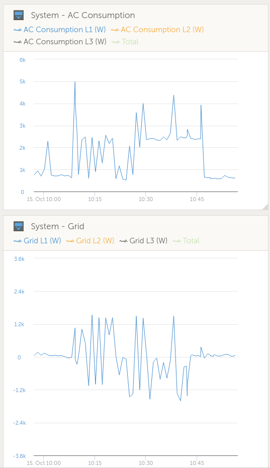
Feedback - I have been told that the unit will be replaced by Victron. Still to be approved by distributors. In the mean time, it seems to be getting worse: At this point in time, the MP II 5000 is generating only about 800 Watt. I have seen the system switch off the inverter completely too. All due to false overheating reading internal to the MP II. These two graphs show that the system draws way too much energy from the grid. All of the consumption is under 4000W. All of it should be carried by the inverter. In stead, the inverter is (falsely) temperature-limiting, and draws energy from the grid. I am planning to give feedback as to how the new unit performs, but this could take about two weeks.


-
Confirmed: I have HW3. Lots of temperature alarms yesterday:

-
Is the HW4 unit better at delivering 4kw outputs? My unit acts like it is a MPII 3000. Works perfectly under 2400watt loads. As the loads increase above that level, it only pushes out 2400w. In terms of the ambient temperature: I see the same thing happen at 4am, when the air temp is about 12C. Where do you see the hw version?

-
It seems my MP II 5000 has the same problem. Exactly the same symptoms. Any update on this?
-
Feedback on the clothes iron - dimmer. The iron' bi-metal temperature regulator still switches off - every time when you put the iron down and there is nothing cooling the plate. So the waveform still look horrible, but with a smaller altitude. The ESS system still sends spikes through to the council, but they are about 800W, where they were 1600W before the dimmer. The spikes look more random. I had a look at the ET112 readings while the dimmer was used and it looked like the dimmer "confused" the ET112 - the watts reading jumped around a lot - and thus the poor MPII had to try to increase or decrease power output continuously.

-
Mmmm remember DC and AC should not run in the same trunking. Should do some planning for the trunking below the MPII.
-
You are nuts... Why? You would be overly complicating the system. pros: could be more resilient to loadshedding, clouds, etc cons: cost, and you would be doubling your failure exposure in the longer run. Any unit fails, your load dies.
-
So I received the 2kw dimmers (bought two from Communica @ R50 each!) and built a short dimmer-extension. Tested with a double toaster and it looks like it will work. Tuesday is the next full ironing day. I will inspect the grid curves and report back.


-
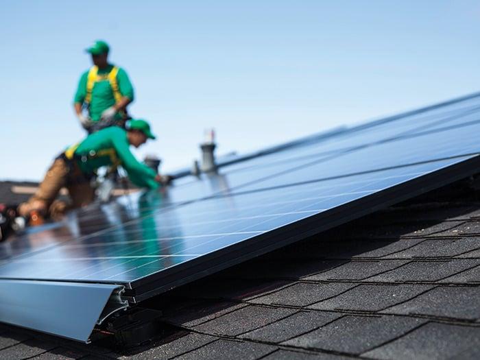
I noticed that Tesla solar panels are often installed with this lip: Which would severely curtail the wind under the panels... Looks nice but seems like a dumb idea.
 😂 Yes, yes - the pun works - good. I am Ironman because my real surname is Stark. I just ordered two of these 2000W dimmers from Communica. I hope to smooth out some of these current push-pull situations.Something like this: https://www.communica.co.za/products/dgm-ac-speed-dimmer-contrl-2000wNew issue: Clothes iron is driving me mad! It has an bimetal strip temp control - 11 seconds on (1500W) , 11 seconds off. It takes about 6 seconds for the 112ET meter -> Multiplus II feedback loop to settle on the grid setpoint. The kwh used for that 6 seconds is about 25% of the total cycle time, which means we pay COJ for using the first 25% when the iron switches on, and another 25% when the iron switches off (and we are sending that power back to the grid) - that adds up to about half of the iron's normal energy cost. It happens much faster than can be seen on the graph that just samples every minute, but you still get a good idea: Help me think of a solution - is there a light switch dimmer that will work if I put it in line with the iron? Let's say I set the dimmer to 50% - the Iron will just heat up to 50%, and the bimetal strip will be always on...? The light dimmers use a switching mechanism which kind of distorts the AC waveform because it can be leading edge or trailing edge dimmers. EG for a trailing edge dimmer - the triac will switch on at the AC zero crossing, and switch off at max voltage (for 50% power). This means every cycle will see a lot more current on every leading edge of the AV waveform. Will the Victron MPII be ok with that? @plonkster ?
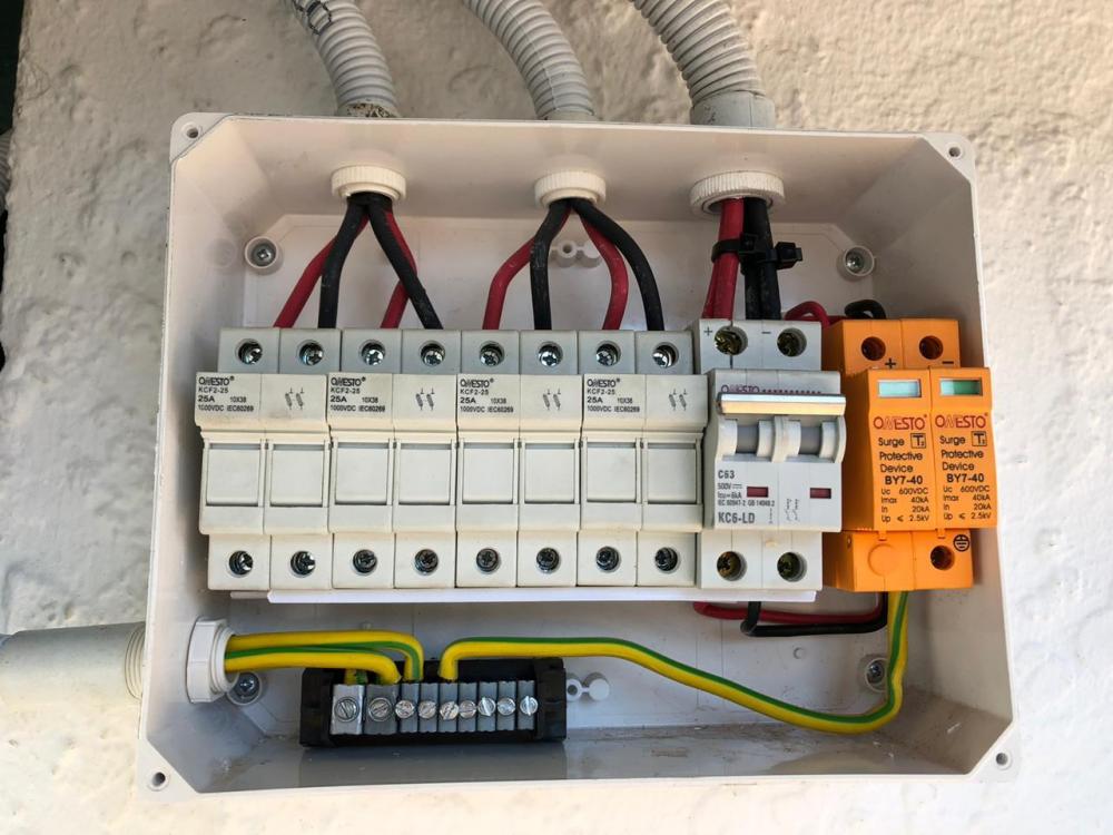
 Very interesting. I never thought of ferrite beads for lightning protection. Ferrite beads are supposed to suppress high frequency noise on DC or low frequency lines - they absorb changes in current, similarly to how a capacitor absorbs changes in voltage. I suppose a lightning strike would cause a fast change in the current flowing in the PV lines - but by that time the surge arrester in the PV combiner box should also be working. I suppose they all add up to make an effective suppression system related to the current surge.In that case - you would probably benefit from a tall standalone lightning pole - like the ones used next to thatch-roofed houses. Interesting note: This image comes from the EE Publishers website, but it is labeled dehn-xxx ..... @plonkster ... You have gone to a lot of trouble. Have you had any hits? Did it survive? I suppose if you don't get any damage you would not really know how many times the lightning protection did its job.
 So would you then rather connect the earth from the combiner box to the house earth only, and not to a spike? Update - I asked my helper to open up some paving and hit the spike into the ground today... So it looks like I will not be using the spike at all - the area where I wanted to insert it into the ground (under paving) is solid foundation concrete. Last option - just take the earth into the roof space and connect it to the house earth. It just seems to be such a long route to take to actually get into the ground: the house earth all goes to the into main DB, and from there back out again all the way to the front of the property - and I don't even know if it is connected to an earth spike there. Single phase 80 amp connection - COJ....Come to think of it - the PV panels are mounted on the mounting rails. The rails are earthed by my combiner box as per the photo above - to a new earth spike. But they are also mounted on the steel roof with metal bolts. And the steel roof is earthed to the house earth anyway. So the panels are indirectly earthed to the house earth....What @plonkster said. My panel mounting grid is for lightning protection. If the lightning strikes close by, I want to try to keep the surges, eddy currents etc isolated from the house 220V and earth as far as possible. Nothing will protect against a serious direct hit.Update: 13 October: Solar combiner box earth connections done using a neutral bar. One earth coming from one solar panel mounting grid, another from another panel mounting grid, and the third goes to a new earth spike - 1M copper, driven into the ground directly underneath the combiner box. Not connected to house earth. An you can see the earth connection to the orange surge arrester. Thanks @Jaco de Jongh for making up the combiner box with all the fuses, DC contactor and surge arrester. I have seen over 40 Amp being drawn from the four strings, and they are wired up with a 10 Amp fuse in the + and - connection for each string. That is really running on the limit for these fuses - I hope they are slow-blow. In the graph below, the current runs at 40 Amp for quite a long time - at one time peaking at 41.7 Amp while the MPPT is searching. Peak power is about 5100 Watt: 100 Amp at 51 V.