


ProjectGKR
Members
-
Joined
-
Last visited
Everything posted by ProjectGKR
-
Hello I have the following setup for sale: 1x Microcare 5kw 48V inverter (with charger disabled). Bought April 2015 and the LCD module was replaced in January 2018. 2x Microcare 60amp MPPT. Bought April 2015 and PIC's replaced in March 2020 (Also have the PIC's for PylonTech batteries) 2x Rubicon 5 string combiner box. (Only used 3 strings on each) 8x Sacred Sun AGM battery 200ah 12v (SP12-200). Bought July 2020 from First National Battery. Also had them tested June 2021 at First National Battery, outcome all healthy. Price: R45000 Location: Wellington, Western Cape
-
@Flip van GreunenSee post https://powerforum.co.za/topic/7819-axpert-inverter-repairservice-center/?tab=comments#comment-90088 regarding Service/Repair Center. SetSolar as mentioned in the post actually troubleshooted component level.
-
SetSolar(http://www.setsolar.co.za/) in Epping repairs inverters. The Technical Manager, Christian Mendaz, was very helpfull and kept me updated daily.
-
Just to close off this topic, I send the inverter for repairs. Problem was with the main board that was replaced.
-
Thanks @Coulomb for all your help. This turned from an inverter repair attempt to a learning experience which is more valuable.
-
With the board removed from the inverter, the resistance from pin 3 to 8-11 is 7.7k With the board removed from the inverter, the resistance from pin 2 to 8-11 is 7.6k and from from pin 1 to 8-11 is 7.7k
-
Thanks @Coulombfor the guidance. I have attached photos of the controlboard. Moment of weakness, hoping for a AHA moment
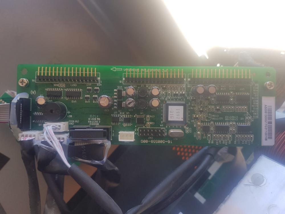
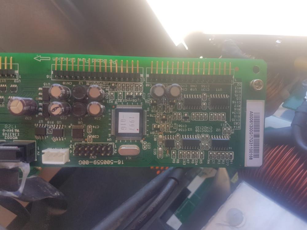
-
Thanks @Quwatush Shams (Suly) and @starmage
-
Replaced all the NTC's and fault remained. Using the Q1 command the 2nd set of 3 digits remained on 102. CN4 when disconnected reflects on the 3rd set of 3 digits. Disconnnecting it it goes to 000 and I also tested that the probe temp changes on CN4 when sticking the probe in ice water. Removing NTC1 reflects on the 4th set of 3 digits. With it removed also showed 000. CN8 when removed did not reflect. Using the schematic for the ntc on the main board, all resistance values are as expected on cn10 pin 1-3 when disassembled. With inverter switched on, I get a resistance reading from pin1 to Ground and pin 2 to ground. Pin 3 to ground getting no reading. I did manage with battery bank voltage above 50v, that the fault after a few restarts disappears, but as soon as it drops under 50v, the fault returns.
-
Thanks @Quwatush Shams (Suly)for the info. Any thoughts on if this is possible via a Victron setup?
-
Yes, double checked. the high 90s was reported with CN4 and CN8 disconnected. only the "Battery Temperature" value dropped to 000 Thanks for the diagram. This assisted in getting a replacement NTC to replace the Transformer NTC. Alos got some NTC replacement probes for the heatsinks. Will be dismanteling and replacing the NTC tommorrow and give feedback.
-
Hello I have a friend that wants to go full Victron. (He has been having endless issues with other brands) He has now replaced his MPPT's with 2x Victron BlueSolar Charge Controller 150/85. This is charging a Lithium 7.4 SolarMD battery. He now wants to replace his 5kw inverter but he is not sure which Victron inverter will meet his requirement of being a hybrid but being able to run Solar first, then utility, and only then Battery (SUB basically instead of the SBU). Any recommendations and what extra Victron components is needed in order for every thing to communicate correctly? Thanks
-
So with the Q1 command now sorted, I decided to add a additional fan using the fan connection at the top of the main board and have it blowing directly on the NTC1. The Temp actually started dropping each time I switch on the inverter, and after about 5x switch the inverter on after auto shutdown the fault error and beep actually stopped at round 67. But it still switched off after 30 seconds. I then changed the battery off voltage as my test battery bank is a bit on the low side, thinking it is due to low voltage, but had no effect as it still does the auto shutdown. I then when it switched on, performed the factory reset via Watch Power. During this process I could hear a relay click and the inverter after its reboot still had no fault and auto shutdown solved. Using the Q1 command again, the temp for all sensors stayed at between 33 - 36. I then decided to move the extra fan to the exit vents on the control board and put all together. And again when switching on, no fault and the Q1 command stayed in the 33-36 temp range.Will let it run for a while and check again later. It is possible the NTC1 is starting to fail. Does anyone maybe have the detail on what exact NTC I need to use to replace the old one?
-
Q1 command is working. (Typo in the Hex for the commands I created and saved to text file for easier use. Sorry @Coulomb my bad) So this is the findings using the Q1 command initial (00000 00000 00 00 00 000 097 030 030 00 00 000 0100 0000 0000 50.00 10 1 060 015 060 005 58.40 000 600 0 0258— (00000 00000 00 00 00 000 097 030 030 00 00 000 0100 0000 0000 50.00 10 1 060 015 060 005 58.40 000 600 0 0258— (00000 00000 00 00 00 000 094 030 030 00 00 000 0100 0000 0000 50.00 10 1 060 015 060 005 58.40 000 600 0 0258õÈ (00000 00000 00 00 00 000 092 030 031 00 00 000 0100 0000 0000 50.00 10 1 060 015 060 005 58.40 000 600 0 0258Ä[ (00000 00000 00 00 00 000 090 030 031 00 00 000 0100 0000 0000 50.00 10 1 060 015 060 005 58.40 000 600 0 0258t1 cn4 disconnect (00000 00000 00 00 00 000 091 000 028 00 00 000 0100 0000 0000 00.00 00 1 060 015 060 005 58.40 000 600 0 0258Ú& (00000 00000 00 00 00 000 097 000 028 01 00 000 0100 0000 0000 50.00 10 1 060 015 060 005 58.40 000 600 0 0258àb (00000 00000 00 00 00 000 099 000 030 00 00 000 0100 0000 0000 50.00 10 1 060 015 060 005 58.40 000 600 0 0258Bœ (00000 00000 00 00 00 000 097 000 031 00 00 000 0100 0000 0000 50.00 10 1 060 015 060 005 58.40 000 600 0 0258’å (00000 00000 00 00 00 000 096 000 031 00 00 000 0100 0000 0000 50.00 10 1 060 015 060 005 58.40 000 600 0 0258ÊÐ (00000 00000 00 00 00 000 094 000 031 00 00 000 0100 0000 0000 50.00 10 1 060 015 060 005 58.40 000 600 0 0258zº (00000 00000 00 00 00 000 092 000 031 00 00 000 0100 0000 0000 50.00 10 1 060 015 060 005 58.40 000 600 0 0258º% cn8 disconnect (00000 00000 00 00 00 000 097 030 031 00 00 000 0100 0000 0000 49.99 10 1 060 015 060 005 58.40 000 600 0 0258Èš (00000 00000 00 00 00 000 099 030 031 00 00 000 0100 0000 0000 50.00 10 1 060 015 060 005 58.40 000 600 0 0258Íî (00000 00000 00 00 00 000 097 030 031 00 00 000 0100 0000 0000 50.00 10 1 060 015 060 005 58.40 000 600 0 0258ì› (00000 00000 00 00 00 000 094 031 031 00 00 000 0100 0000 0000 50.00 10 1 060 015 060 005 58.40 000 600 0 0258˜\ (00000 00000 00 00 00 000 087 031 031 00 00 000 0100 0000 0000 50.00 10 1 060 015 060 005 58.40 000 600 0 0258žþ (00000 00000 00 00 00 000 087 031 031 00 00 000 0100 0000 0000 49.99 10 1 060 015 060 005 58.40 000 600 0 0258ºÿ cn4 & cn8 disconnect (00000 00000 00 00 00 000 096 000 031 00 00 000 0100 0000 0000 50.00 10 1 060 015 060 005 58.40 000 600 0 0258ÊÐ (00000 00000 00 00 00 000 096 000 031 00 00 000 0100 0000 0000 50.00 10 1 060 015 060 005 58.40 000 600 0 0258ÊÐ (00000 00000 00 00 00 000 096 000 031 00 00 000 0100 0000 0000 50.00 10 1 060 015 060 005 58.40 000 600 0 0258ÊÐ (00000 00000 00 00 00 000 093 000 031 00 00 000 0100 0000 0000 50.00 10 1 060 015 060 005 58.40 000 600 0 0258â (00000 00000 00 00 00 000 091 000 031 00 00 000 0100 0000 0000 49.99 10 1 060 015 060 005 58.40 000 600 0 0258v{ (00000 00000 00 00 00 000 088 000 031 00 00 000 0100 0000 0000 50.00 10 1 060 015 060 005 58.40 000 600 0 0258X What is interesting is that disconnecting cn8 had no effect on the output
-
U1 74 10 is what the display shows The model no on the label on the side is Axpert 5000-48. It also notes that it is made for Solar MD PTY Ltd
-
It is possible that newer firmware version implements this? What resistance value is expected for the NTC1 when removed from the main board? One I removed is 30.5k ohm. When taking a resistance measurement on the main board on the contacts where the NTC1 is removed I get a reading of 6k. All the boards are removed from the main board.
-
Using QPIGS command I get a value 0102 for the Inverter heatsink temp. Will ntc on mppt as test work on inverter side?
-
Used the incorrect bps. Sending the Q1, I get the folllowing in AccessPort terminal: Hex: 28 4E 41 4B 73 73 0D Char: (NAKss. And when the inverter shutdown, the hex 00 gets added
-
Hello Any repair/service centers for axpert inverters in cape winelands/capetown area?
-
Thanks @Coulomb I removed the mppt completely and tried again but fault remained. I also as per service manual left cn4 & 8 disconnected and fault remained. In order for me to measure the resistance of ntc1 at the transformer I had to completely disassemble the inverter, so the control board was disconnected when taking measurement. I tried the Q1 command via serial port using auto send in Access port software set at 8000ms and at 1000ms but no response from inverter and it shuts down after 30 seconds. I believe as mentioned that the control board the issue here and will check the components on it but I think it is end of the road for the inverter, unless I can find a repair centre in Capetown.
-
Thanks @Coulomb, will give the Q1 Command a go. Sorry, should have mentioned it is for another setup and not the one as per my signature.
-
HelloWhen switching on inverter, it continuously beeps with fault led on with code 02 and then after short while switches off.As it has been in use for 2 years now, I did blow out dust first but did not solve fault.Looking at the service manual, I looked at the NTC section for fault code 02. All resistors are in the expected ranges. The ntc on cn4 & cn8 unplugged is above 14.2 & 14.8, not sure if must be exactly 15 as per manual? The ntc1 on the main board value is 7, but i haven't removed it from the board yet. Must I also like with cn4 & 8 remove it in order to get correct reading?Any thing else I can check?
-
7 of the 8 batteries in my current setup are out of warranty as I purchased it in May 2018. I went down from 3 to 2 banks Nov last year (only purchased one new battery to get to 2) The 2 batteries that failed are all the May 2018 purchased batch
-
Hello So after 3 months 2 batteries again has gone bad. One in each bank. I have now contacted microcare to find out if I can get updated firmware for my Mppt's and to also get it ready for Li Ion. What size Li Ion would be the best for my current setup of 2x 60A mppt's and 9x 300W panels facing east and 9x 300W panels facing west? I am not worried about going off grid, I just want something that is reliable as I am currently spending all my capital on batteries. Thanks
-
Asking myself the same thing now. Initially I measured the voltage on each battery during boost and some batteries was showing a higher voltage, and then I ended up setting it at 14.5V. With what I learned sofar, 14.7V would probably the best mid way looking at Battery info:Cycle Use: 14.6-14.8V Standby Use: 13.6-13.8V Maybe up the Float to be 13.7V aswell


