Giel
Members
-
Joined
-
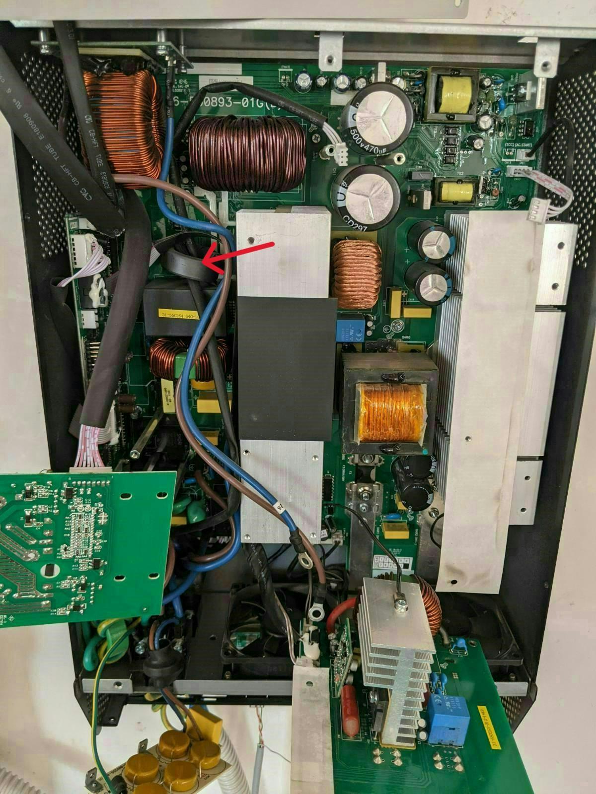
This photo shows how the connection wire was wound around the ferrite core with at least 4 turns.

-
Here are photos of where in the inverter I found the wire that was protected by the ferrite to show the approximate location and the turns in wire.

-
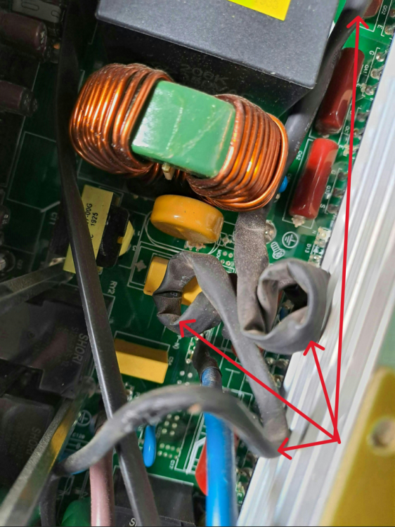
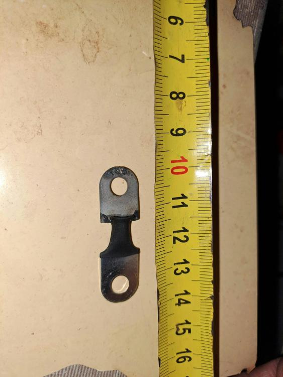
Coulomb I found two photos on the Aussie forums at PIP inverter repairs and hardware modifications - Page 26 - AEVA Forums posted by calida82. I am adding them here with arrows pointing to the ferrite toroid named Aus Photo 2 Arrow and Aus Photo 3 arrow. I am also adding photos I took of the small piece of ferrite. I will be adding my MKS II photos in another reply. Giel



-
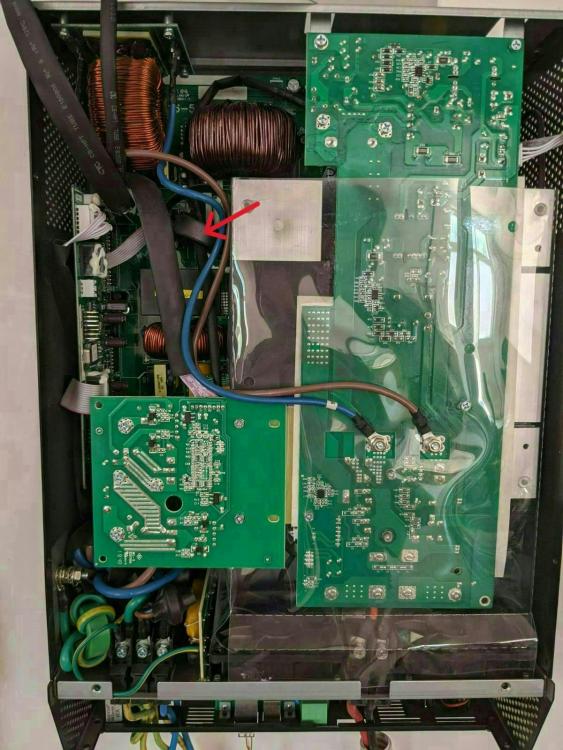
I remember the location of this 25% ferrite toroid to have been in the area "encircled" in the picture and suspect it to have been on the cable with the arrow, but my cable was much longer and once could clearly see it was turn around a ferrite toroid.

-
Coulomb Thank you for your reply. The batteries are indeed connected in parallel (positive to positive, negative to negative with short 50mm² battery cable). The cables to the battery disconnect fuses are the same length with the + coming from the top battery and the - from the bottom battery. My conductors are all 50mm². I have 2 x 50mm² cables from positive to my battery disconnect fuses and 2 x 50mm² cables from negative to my battery disconnect fuses. These four cables connect to 2 disconnect fuses. One positive and one negative cable to each disconnect fuse for the first 2 inverters. The battery disconnect fuse for the 3rd inverter is then fed from the battery disconnect fuses of the first two inverters with short 50mm² cables. In other words: + from fuse 1 to + of fuse 3, + of fuse 2 to + of fuse 3 and - of fuse 1 to - of fuse 3, - of fuse 2 to - of fuse 3. All these four wires are very short 50mm² cables. These are creating a DC "bus bar". When I installed the 1st two inverters, I made sure the battery cable lengths from the batteries to the battery disconnect fuses and to the two inverters are exactly the same length. In adding the 3rd inverter, I could not achieve this. The cables from battery disconnect fuse 3 to inverter 3 is about 25 cm longer than those to the two other inverters. My question and messages are long, but I must add this extra detail: The 3rd inverter is a refurbished inverter, which I bought for my son around Jul 2022. I installed one of the same Narada batteries for him. Th system was used as a UPS to help him with our South African grid loadshedding, and they had a small baby. The system had no PV panels. To cut a long story short, the inverter was not working 100%. It seemed to struggle to take the load when the grid went off. I took the unit back to the supplier and it was checked and cleared of any flaws. My son moved 5 months later, and I recovered all equipment, used the battery at my house and boxed the inverter and all switches. I unboxed the inverter now and when I picked it up, I could hear something falling around inside. I had no choice than to open it, my first time opening one of these. I checked all the available service manuals I could find. I found a very small piece of ferrite toroid inside. I could not locate the other bigger part of it. It was about a 25% piece of a full ferrite toroid core/ring with outer diameter of about 35.5mm, inner diameter of about 23mm, width of about 12.7mm and thickness of about 6.2mm. I could get the outer and inner diameters by taking this small piece and drawing a circle on a piece of paper, measuring it with a vernier and then comparing against what is available in the industry. Having looked carefully, I could see where this came from. It was used on one cable between two boards and must be some sort of noise suppression. I cannot tell you now between which boards it was as I did not check it. It came from a longish cable to the left of the left heatsink below the MPPT and under a small board mounted to the left bottom of the MPPT. I tried to locate this ferrite core/ring on pictures posted on this forum and the Australian forums and in service manuals but could not find any and decided to close up the unit and test it. The unit switched on and I could change all settings to match my other two inverters. Having changed the settings, I shut it down and completed all the outstanding wiring and also did the revised parallel connections. On starting up all three inverters, this 3rd inverter did not want to switch on at all. I had to restore the parallel wiring to two inverters and then opened this 3rd inverter. I found that the main battery positive fuse was not properly secured. I removed it and could clearly see traces of arcing between the fuse and the top connection on the PC board. I am attaching a photo of the fuse before cleaning it. I cleaned the fuse and sprayed it with electro cleaner, spray electro cleaner on the contact on the PC Board, put the fuse back and secured it properly and walla, the inverter switched on. This must have been the fault we detected way back in Jul 2022. I restored all the parallel wiring, started everything up and load tested the capacity and since then all is fine. This is about two weeks ago. I am wondering whether this ferrite toroid or the fuse or both might be contributing to my switching issue. I am suspecting the fuse as it does not seem to be the original fuse, has no identification on it and I could not find out the specifications in any user or service manual and our local Mustek supplier plus two inverter repair shops would not tell me. I suspect this is a 200A 58V mega fuse. Its overall length is about 35mm and the distance between the center of the two mounting holes is about 25mm. I am feeling that this fuse must be replaced as it could cause a voltage drop based on the arcing surface I had to clean, so I will appreciate confirmation of the specifications of the fuse. Below is a picture of which fuse I think it must be and I am attaching its datadsheet for confirmation. Once I find a replacement fuse and have to open it, then I can determine exactly which cable this ferrite toroid was fitted on, between which boards this cable is connected and I can take pictures as well. That way you might be able to confirm whether this ferrite is important to replace. I noticed that one gets lots of ferrite toroid's with the same dimensions, but all having different electrical specifications. In the case that this one cannot be properly identified, I can then open one of the other inverters to check whether it has a similar one, take a picture of where it is fitted and take some measurements. I hope this message is clearer than mud and that you will be able to assist. Thanks Littelfuse-Datasheet-153-BF1-58V-r4-0.pdf

-
I had 2 of these inverters installed in Dec 2019 with 2 strings of 7 x 325W PV panels. I added PV panels along the way and upgraded my system now in Jan 2025 to be as follows: 3 x MKS II in parallel, Inverter 1 (Master) with 7 x 325W panels facing north, Inverter 3 with 7 x 325W panels facing north and inverter 2 string 1 with 7 x 330W panels facing north and string 2 with 7 x 330W panels facing west. I have 6 x Narada 48NPFC100 batteries. I use a Raspberry pi for monitoring with the latest ICM software version (looks like 1.25). Total inverter peak capacity = 15kW, total PV capacity 9.17kW and total battery capacity = 4.8x6=28.8kWH (23 kWH usable to 20% depth of discharge) I did this upgrade from 2 to 3 inverters to make provision for peak usage exceeding 10kW (which happened occasionally) and to make provision to install inverter-based air conditioners in the near future. I tested the capacity of the upgraded setup to about 14.6kW from the battery and solar with the AC grid disconnected. Before I did this upgrade, I used to run my setup in off-grid mode as I switched the AC Grid off. I could manually switch the AC grid on if I was at home or remotely switch it on using a Sonoff device connected a suitable contactor. This worked fine, but I had to monitor the batteries to make sure it does not discharge too much when we were away from home, say on weekends or on holiday. With the upgraded setup, I wanted to automate this to allow the inverters to make that decision to allow me not to have to monitor the system regularly. Iset the following settings: 1. In the "Control Settings" menu under "Settings", selected "Time For Different Modes" to be ON, selected "SOC for Control" to be on and ticked SBU in all cells in the table. 2. The inverter settings are: "Charger source priority" = Utility and Solar, "Output source priority" = SBU, "AC input range" = UPS, "Battery type" = User, "Back to grid Voltage" = 46.0, Back to discharge voltage" = 48.0 I switched the AC grid on and tested the upgraded setup. I then noticed that the system would occasionally switch from battery to grid during the day while the battery is almost fully charged and with the sun shining. I investigated and noticed that this seems to happen with high loads (more than 10kW) and when a cloud obscures the sun. After about 10 minutes or so, the system will switch back to battery. Then there was a case where the load was about 13kW and no switching happened. On another day when the load was again above the 10kW mark, the systems switch to grid again. I first thought it was the settings related to Back to grid Voltage and Back to discharge voltage. These were higher, but I changed them on all inverters to the voltage above. I also studied the Narada battery specifications and noticed that their disconnect voltage is about 40.5V for older batteries. This seems to be higher for the newer Narada batteries. I then monitored the battery voltage while increasing the load to see whether the voltage drops to cause a switch to grid. The battery voltage drops under high loads, but never got close to 46V, in fact, it was above 48V. Based on my findings, I am considering going back to my old ways of just switching the grid off. Our average grid usage is about 0.7 kWh per day since Dec 2019. Does anyone have an explanation why this is happening (switching from battery to grid) and what I could do to rectify it?
-
Monday, if the weather permits, the number of PV panels will be increased to almpst double the PV capacity. I suspect that we will notice a significant improvement in yield from the current 4 east facing panels as this will be increased to 6. Then as mentioned above, another west facing string with 8 pnaels will be added. From Tuesday we will monitor this 500W power decreasing phenomenon again. If it still happens, we will do a number of things to find the cause namely: 1. A new confirmed legit, reputable installer is now contracted and will do the PV instalaltion on Monday. Maybe he can help Monday already, depending on the time of day they complete the installation. It could potentially be wiring or a setting. 2. If this persists and the cause is not identified, then I will go to a friend here in Pretoria and take screen shots of all the settings menus to compare. 3. If that does not identify the cause, then the position of the CT coil might be the cause. I suspect it is currently installed on the incoming mains in the DB box in the garage, next to the two 5kW inverters. If so, then maybe the metal box or inverters itself (EMI) or something might be interfering with the inductance of the coil and cause incorrect measurements. This is far fetched, but not impossible. I noticed with my installation (Mecer Axpert inverters) that the EMI from the inverters had an influence on the remote receiver of my alarm system. I had to move the remote receiver away from the inverters. If this is the case, then we will have to accept it as we might not find an alternative position to install it.
-
I did untick the grid charge from 9h00 to 17h00, but had to put it back today as the sun was not that great in Cape Town area and there was more load due to house cleaning activities, doing washing, tumble drier, ironing, etc. Will try again once extra panels are installed.
-
I am in Pretoria and my son in Somerset West. I hope the additional panels will be installed within a week or so. Then we will see if the response regarding the 500W is the same or not.
-
-
Hi Talia I am not sure from which inverter MPPT the drop is coming from. I could have checked it, but cannot remember. You are 100% correct about the 4 panels being close to the inverter startup voltage of 150V. We are busy addressing this and this should be sorted soon. These 4 panels are east facing and we can add two as that is the space available on that roof. We will also add 8 more panels on the west facing roof on MPPT2 of the master. This will then be the maximum solar capacity the roof space can handle. The total solar will then be as follows: Master MPPT 1: now 4 panels x 425W (1700W) to increase to 6 panels x 425W (2550W) Master MPPT 2: now 0W to increase with 8 panels x 425W (3400W) Slave MPPT 1: now 8 panels x 425W (3400W) and will stay like so. Total now 12 panels x 425W (5100W) to increase to 22 panels x 425W (9350W). This is potentially an overkill, but only the slave 8 panels are north facing. The master MPPT 1 panels are east facing and the master MPPT 2 panels will be west facing. So the capacity is kind of the slave MPPT 1 panels (3400W) plus either the master MPPT 1 panels or the master MPPT 2 panels or something inbetween. Giel
-
-
Hi Scorp007 We are using grid time settings as shared with Tim. I cannot remember wat the SOC was when the grid came on. Giel
-
Hi Tim. Here are the current time settings Giel

-
My son had 2 x Deye 5kW inverters installed in parallel with 2 x Deye 5.32 kWh batteries. The slave has 8 x 425W panels (3400 W) on one string and the master has 4 x 425W panels (1700W). We will be adding busy to get this 1700W changed as the voltage is a bit low. We will be adding 2 more 425W panels as this is what the roof space allows. This was installed in a new built house and the grid was not conencted yet. My son moved in a few days ago and could track the production. Yesterday the grid was connected. The moment the grid came on, the total PV went down by about 500W. This morning I noticed that the PV power curve is starting later than yesterday. I montired it and then asked my son to switch off the incoming grid mains switch. Immediately the production increased by about 500W. Is this normal? If not, why is this happening and what needs to be changend?
-
Any other simple/easy ideas to load test the panels in order to determine their yield?
-
Coulomb, why is it dangerous? I have done this test with a 3kW geyser element judt yo see if the element will hear up and had no issues?