


Tracsec
Members
-
Joined
-
Last visited
-
Did you manage to get any assistance here?
-
 Tracsec reacted to a post in a topic:
Sunsynk 8kw Inverter and CHINT DDSU666 single phase smart meter
Tracsec reacted to a post in a topic:
Sunsynk 8kw Inverter and CHINT DDSU666 single phase smart meter
-
I have the same issue. Bought 6x d1 dimmers and 6x rf controls for a client. 1 for each area. They require to use the app and the rf remote. Worked great initially but now after a month the client complains the lights switch on and off randomly in the middle of the night during the day or whenever it pleases, i can confirm this myself having checked . The circuits are on backup on the essential side of the inverter and not once has the devices ever powered down as they all have a constant power source. This is a serious issue and we are actually going to pull the devices out now and replace with something else. If i had know this issue beforehand i certsinly wouldnt have touched the particular product. Certainly not something I expected from Sonoff.
-
What is the standard common connection methods for PE to and from the Deye/Sunsync Are the Earth connections and chassis earth common across all points? I've seen conflicting information and pictures here and elsewhere with installs only having earth fitted on the grid pe terminal and no earth connected on the load out. Others with seperate earths for both grid and load outputs and then others with no earth at all on the pe input blocks and just earth wired to the chassis. What is the correct method?
-
-
-
-
Wondering if anyone can help with an odd BMS Issue with the combination of the below equipment combination. Simple backup Inverter System - No Solar 1x Growatt SPF5000TL HVM 1x Dyness Powerbox - A48100 Installation was completed late last year, on initial installation and setup of the battery as per the Dyness manual it is recommended that dip #2 & #3 are switched ON (SPF -HVM Series) for correct communication between battery and inverter, the inverter programmed to LI with communication protocol 02 would not communicate with the BMS - code 20 and code 04. After this fault supplier recommended Dip #2 ON only (SPH/SPA Series) which then established coms and I could see SOC values etc This dip switch setting initially appeared to work and the system was happily functional and faultless for roughly 2 days when the inverter then started disconnecting the supply and reconnecting again after about 30 sec each day, being in the middle of festive season there was not much I could do but lived with the disconnection whilst still maintaining backup- the cause of the fault registering code 04 and 20 again each time the inverter disconnected and the reconnected after re establishing BMS! Fast forward to today the inverter disconnected but would not reboot automatically as it had done previously numerous times (completely dead until physically restarting the unit and battery with the power switches etc), a reset of the unit, re establishing or changing of BMS settings for the battery / Inverter, whatever has been tried will not allow the unit to communicate once again with the battery in LI Mode and the inverter shutdowns, the inverter or possibly battery side of the BMS appears to be completely faulty now with code 04 and 20 being permanently displayed. The connecting cables supplied with the dyness pack have both been checked and pin outputs appear correct between the inverter and battery BMS as well as the CAN and Rs485 Protocols - non however will work although it did initially the first 2 days🙈 In order to get the system functional again US2 (user defined option 2) has been configured instead temporarily and I have set all the charge characteristics manually and the inverter and battery are working and online again Does anyone possibly have the same setup or similar experience and guidance in this case, before i pull the unit out and send it back to the manufacturer?
-
Yes dc switch on and green button depressed.
-
-
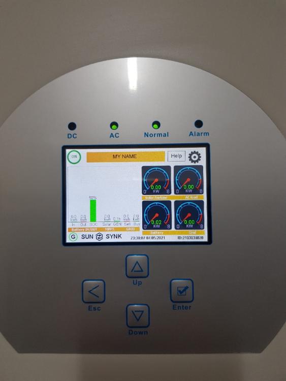
Just finished completion of an 8kw Sunsync with solar and US3000c battery On final commissioning and switch on of the system for the first ti.e I have 3 issues. 1. The system initially said no battery (connected via rs485) after switch to CAN would then communicate to the battery but now doesnt appear to want to charge the battery. This is setup correctly in the menu and can be seen with the relevant figures and SOC rates in the bms li menu - so it looks like its communicating. Attached screenshot shows the status of this battery and the inverter just stays in this current situation without charging. 2. The load output is not sending power out to the essential circuits even though the inverter is powered correctly,as such I'm currently having to use the change over switch to eskom side until I can find out why there is no power out on the load side even though the menu indicates there is 230v. 3. CT is not showing up in the menu. There are inconsistencies in the manual and on the actual board as to where this should be placed but trying all the relevant options as discussed elsewhere here on the forum it still doesn't work. Is it possible because the ct is not being sensed that the inverter is not "switching" the loads or powering the battery and is waiting for this feedback to determine how to operate or have I got a dead unit straight out the box? I've racked my brain trying to figure this out I'm sure this must be a very simple problem to fix but being the very first sunsynk fitted I'm not familiar with the possible problems or what to look at to try resolve this.
-
-
-
 Yellow Measure reacted to a post in a topic:
Earthing of solar panels. Earth cable in same conduit as pv cables?
Yellow Measure reacted to a post in a topic:
Earthing of solar panels. Earth cable in same conduit as pv cables?
-
Thank you. I may very well have to do it like this. 3 storeys up though so if I can avoid this I will try!
-
Tracsec reacted to a post in a topic:
Earthing of solar panels. Earth cable in same conduit as pv cables?
-
Hi Guys. A rather dumb question I guess but could not find any info on this aspect. Earthing on solar panels. Is the earth wire from a regulation point of view allowed to be installed within the same conduit as that of the PV Cables down from the roof or should this be physically separated to increase possible lightning induced damage between the two? Or possibly run it outside on the steel conduit?

