SolarConvert
Members
-
Joined
-
Last visited
Everything posted by SolarConvert
-
Thanks @shanghailoz One command that the Deye inverter does issue is the following, but I have yet to decipher what this one does. Command: 7e 01 43 00 fe 0d Response: 7e 01 43 94 00 02 0e 10 01 02 03 e8 02 02 0d ac 03 02 0a f0 04 02 03 e8 05 02 0c 1c 06 02 15 4a 07 02 03 e8 08 02 14 c8 09 02 11 94 0a 02 03 e8 0b 02 13 88 0c 02 1f 40 0d 02 03 e8 0e 02 1b 58 0f 02 1f 40 10 02 03 e8 11 02 1b 58 12 02 00 69 13 02 0f a0 14 02 00 5f 15 02 00 32 16 02 0f a0 17 02 00 3c 18 02 00 69 19 02 0f a0 1a 02 00 5f 1b 02 00 32 1c 02 0f a0 1d 02 00 3c 1e 02 00 8c 1f 02 0f a0 20 02 00 87 21 02 00 0a 22 02 00 0f 23 02 03 20 24 02 01 f4 de 0d I can see the data map but do not yet know what each item means. Reformatted: 7e 01 43 94 00 02 0e 10 01 02 03 e8 02 02 0d ac 03 02 0a f0 04 02 03 e8 05 02 0c 1c 06 02 15 4a 07 02 03 e8 08 02 14 c8 09 02 11 94 0a 02 03 e8 0b 02 13 88 0c 02 1f 40 0d 02 03 e8 0e 02 1b 58 0f 02 1f 40 10 02 03 e8 11 02 1b 58 12 02 00 69 13 02 0f a0 14 02 00 5f 15 02 00 32 16 02 0f a0 17 02 00 3c 18 02 00 69 19 02 0f a0 1a 02 00 5f 1b 02 00 32 1c 02 0f a0 1d 02 00 3c 1e 02 00 8c 1f 02 0f a0 20 02 00 87 21 02 00 0a 22 02 00 0f 23 02 03 20 24 02 01 f4 de 0d Since this is the first call that the inverter makes to the BMS, these must be the parameters that the inverter expects back from the BMS. When I have time I will try to dig deeper, just posting it here for now.
-
I have Float set to 52.5V and Absorption set to 53.5V. I used to have them on 51.5V and the battery never fully charged. This is for a Narada 48NPFC100. It looks like the Deye inverter can communicate with the Naradata battery uses a Shinwa BMS however the Tian Power BMS (which is what I have) is not supported (yet). You can check a few pages back on which wires to crimp if your battery uses a Shinwa BMS. The SOC on the inverter will definitely vary from the true SOC reported by the BMS if there is no BMS comms - mine has varied by up to 30%. Not yet. The last contact I had with Deye support was that they would consider adding support for Tian Power BMS for Narada batteries if there was enough demand. I gave them the info that they asked for and have not heard anything since. There have been several people on this thread that have got the BMS comms to work, but if you have a Tian Power BMS on your Narada batteries you're probably out of luck for now. You can try to find out what BMS you have by either crimping the inverter-to-battery cable according to the posts on the previous pages to see if it works or by trying out the two types of BMS software attached on the previous pages and see which works for you.
-
Mine looks exactly like the one you got from Takealot except that it also has the handles on the sides like in your second photo of your original/current batteries.
-
Here is the Tian Power BMS protocol post I wanted to put together: I will update that thread with function 67, which is what the Deye inverter uses to scan for batteries under Lithium mode 9.
-
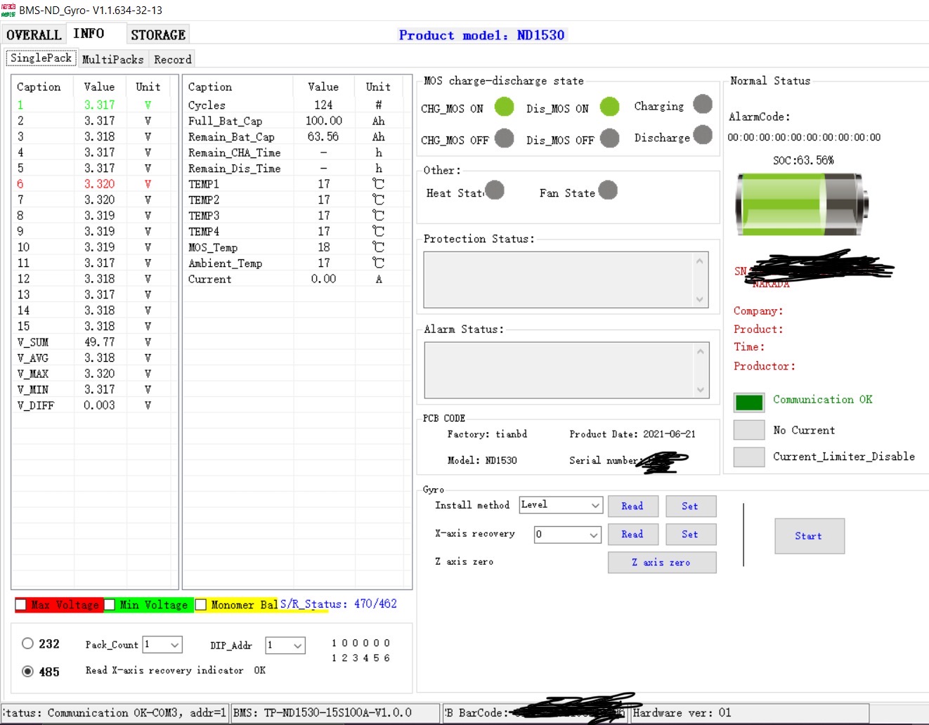
Hi all, I thought I would document my findings of the Tian Power BMS protocol used in my Narada 48NPFC100 battery whilst I was attempting to establish why it did not work with my Deye inverter. Of note is that the exact same battery model is known to use a Shinwa BMS as well, but mine uses a Tian Power one, specifically TP-ND1530. Firstly I wanted to thank @shanghailoz for documenting the same thing here for the Revov batteries, which also use a Tian Power BMS, without which I would have struggled a lot more. Also thank you @zivva for pointing me in the right direction for the BMS manufacturer. I also peeked at the code of the BMS software to decipher how certain fields are calculated. The protocol follows. Preamble Firstly, all data sent appears to have a header, body and CRC check. For example: 7e 01 01 00 fe 0d The first byte is either 7c or 7e according to the software. In my case it is always 7e. The second byte is the DIP switch setting on the battery and corresponds to the following in the software: The third byte is the function code, which you will see several examples of below, such as "read data", "read BMS time", "read BMS version", "read serial number". The fourth byte is the length of the payload supplied as part of the function call - most "read" type functions will not include a payload and this parameter will be 00, but the "write" functions would have a payload. If there is a payload, it would follow this byte. The last two bytes are the CRC check. The response is structured in a similar way: 7e 01 01 56 ... f2 0d The first three bytes are an echo of what the request was, the fourth byte indicates the response length followed by the response bytes, and finally we have the CRC check. Function 1 - Read data 7e 01 01 00 fe 0d This allows you to read almost everything that is displayed on the first tab of the BMS software. The response will look as follows: 7e 01 01 56 01 0f 0c e1 0c e2 0c e2 0c e3 0c e3 0c e5 0c e5 0c e4 0c e4 0c e4 0c e2 0c e2 0c e2 0c e3 0c e5 02 01 75 30 03 01 16 74 04 01 27 10 05 06 00 44 00 45 00 45 00 44 40 46 20 45 06 05 00 00 00 00 00 00 00 00 00 00 07 01 00 81 08 01 13 54 09 01 27 10 0a 01 00 00 f2 0d The response body for this function is a data map structured as follows: data entry index, number of high/low byte pairs, the high/low byte pairs. Data 1 - Cell count and cell voltages 01 0f 0c e1 0c e2 0c e2 0c e3 0c e3 0c e5 0c e5 0c e4 0c e4 0c e4 0c e2 0c e2 0c e2 0c e3 0c e5 The second byte is the number of cells - this is 15 for a 15 cell battery like mine or 16 cells for Revov. The individual cell voltages follow as high/low pairs which need to be divided by 1000, for example, 0ce1 maps to 3297 which means 3.297V. Since my battery has 15 cells, there would be 15 individual cell voltages. Data 2 - Current 02 01 75 30 This is a tricky one. 7530 hex maps to 30000 decimal. The BMS software works it out as: current_in_amps = (30000 - value_of_item_2) / 100 This item therefore has an offset of 30000 and a scaling factor of 0.01. So when the charge current is 0, the BMS will return 30000, therefore (30000 - 30000) / 100 = 0 amps. When the charge current is 10 amps, the BMS would return 29000, therefore (30000 - 29000) / 100 = 10 amps. When the charge current is -10 amps, the BMS would return 31000, therefore (30000 - 31000) / 100 = -10 amps. Furthermore, charge/discharge time remaining is calculated based on max battery capacity in amps divided by current in amps. Data 3 - Remaining capacity 03 01 16 74 This value needs to be divided by 100 to get Ah. In this case I have 1674 hex or 5748 decimal, so 57.48Ah left of my 100Ah battery, therefore the SOC is 57.48%. Data 4 - Full capacity 04 01 27 10 Divide by 100 to get full battery capacity in Ah. 2710 in hex is 10000 in decimal, so I have a 100Ah battery. Data 5 - Temperatures 05 06 00 44 00 45 00 45 00 44 40 46 20 45 In my case there are 6 temperatures corresponding to the following screenshot: In the Revovs the number of temperatures listed are different. The last two appear to be important ones. Each temperature value is calculated as: temp_value = (bms_temp_value & 0xFF) - 50 Data 6 - Alarm bits 06 05 00 00 00 00 00 00 00 00 00 00 These can be mapped to (a) very specific alarm code(s). I can get these if there is interest. Data 7 - Cycles 07 01 00 81 This represents the number of cycles of the battery, so 129 in my case. Data 8 - Voltage 08 01 13 54 The total voltage of the battery. The number needs to be divided by 100, so 49.48V in my case. Data 9 - State of Health 09 01 27 10 The SOH of the battery. Needs to be divided by 100, so 100% in my case. Data 10 - ALM bytes 0a 01 00 00 This corresponds to the ALM light on the battery and what it means. Function 67 - Read protection parameters Request: 7e 01 43 00 fe 0d Response: 7e 01 43 94 00 02 0e 10 01 02 03 e8 02 02 0d ac 03 02 0a f0 04 02 03 e8 05 02 0c 1c 06 02 15 4a 07 02 03 e8 08 02 14 c8 09 02 11 94 0a 02 03 e8 0b 02 13 88 0c 02 1f 40 0d 02 03 e8 0e 02 1b 58 0f 02 1f 40 10 02 03 e8 11 02 1b 58 12 02 00 69 13 02 0f a0 14 02 00 5f 15 02 00 32 16 02 0f a0 17 02 00 3c 18 02 00 69 19 02 0f a0 1a 02 00 5f 1b 02 00 32 1c 02 0f a0 1d 02 00 3c 1e 02 00 8c 1f 02 0f a0 20 02 00 87 21 02 00 0a 22 02 00 0f 23 02 03 20 24 02 01 f4 de 0d This is another data map which ultimately gets translated into the following, with the necessary scaling factors applied: { "cell_ov_start": 3.6, "cell_ov_delay": 1000, "cell_ov_stop": 3.5, "cell_uv_start": 2.8, "cell_uv_delay": 1000, "cell_uv_stop": 3.1, "pack_ov_start": 54.5, "pack_ov_delay": 1000, "pack_ov_stop": 53.2, "pack_uv_start": 45.0, "pack_uv_delay": 1000, "pack_uv_stop": 50.0, "charge_oc_start": 80.0, "charge_oc_delay": 1000, "charge_oc_stop": 70.0, "discharge_oc_start": 80.0, "discharge_oc_delay": 1000, "discharge_oc_stop": 70.0, "cell_ot_start": 55, "cell_ot_delay": 4000, "cell_ot_stop": 45, "cell_ut_start": 0, "cell_ut_delay": 4000, "cell_ut_stop": 10, "env_ot_start": 55, "env_ot_delay": 4000, "env_ot_stop": 45, "env_ut_start": 0, "env_ut_delay": 4000, "env_ut_stop": 10, "mos_ot_start": 90, "mos_ot_delay": 4000, "mos_ot_stop": 85, "capacity_low_start": 10, "capacity_low_stop": 15, "volt_diff_start": 800, "volt_diff_stop": 500 } Function 51 - Read BMS version The request is as follows: 7e 01 33 00 fe 0d The response body is a string, such as: 7e 01 33 18 54 50 2d 4e 44 31 35 33 30 2d 31 35 53 31 30 30 41 2d 56 31 2e 30 2e 30 2e 0d Which in my case maps to: TP-ND1530-15S100A-V1.0.0 Function 66 - Read PCB barcode Request: 7e 01 42 00 fc 0d Response body is a string as above. Function 220 - Read serial number Request: 7e 01 dc 03 06 00 00 c2 0d Response body is a string as above. Function 69 - Read BMS time Request: 7e 01 45 00 fe 0d Response: 7e 01 45 06 16 07 08 14 3b 16 48 0d To convert the above to a valid date time, prepend "20" and then concatenate the rest of the bytes which represent yy, MM, dd, hh, mm, ss, so in the above example: 2022-07-08 20:59:22. There are many "write"-type functions too but I would be wary of using those. I hope the above is useful to someone. I will post more useful ones if I find any.


-
I used a trial of Advanced Serial Port Monitor to monitor: BMS software on a laptop communicating to the battery, and separately Inverter comms to the laptop, the laptop just never responds to the inverter, but I do get the "scanning" requests from the inverter logged with the various lithium modes. However, I do not think your scenario will work for multiple reasons: There is nothing to sniff out on pins 7&8 (or any pins) if the goal is to monitor the inverter. A valid MODBUS request needs to be sent to the inverter from whomever/whatever wants to monitor it, requesting one or more register values. The inverter will then respond with register values. The inverter does not by itself "broadcast" its register values without being asked, at least not via the BMS485 port. The behaviour of the BS485 port changes when set to lithium mode 16 and the response fails CRC checks when requesting register values. This I tried without a battery connected to the BMS485 port some time back, so even if one were able to split that port into two, with pins 2 & 1 for the battery and pins 7 & 8 for monitoring, you'd still need to send a request to read registers via pins 7 & 8 and the response would fail CRC checks. I believe pins 2 & 1 are bonded to pins 7 & 8 on the BMS485 port, so the latter combination are not "separate lines" for putting them to use for a different purpose - the way I understand it is that you would use pins 2 or 7 and pins 1 or 8 for the RS485-A and RS485-B signals respectively. The only exception to this appears to be the Sol-Ark 12k (Outdoor) which appears to have CAN bus and RS485 pins on one RJ45 port and this does indeed require a splitter to use the two different protocols. I stopped evaluating this option of monitoring the inverter at the failed CRC checks. Maybe the invalid response can be examined further, but I doubt that Solar Assistant / ICM would be update to cater for this scenario even if the response were somehow valid. That being said, I'd be very happy to be proven wrong about the above since I'd be in the same boat as you (with a used up BMS485 port, wanting to monitor the inverter, and have the data logger plugged into the RS232 port) once I do get BMS comms working. Edit: You actually don't need a serial port monitor to test the monitoring bits out with lithium mode 16 and the BMS485 port - you just need a tool that can send a MODBUS request to the inverter whilst you are connected to it (via USB, etc) whilst the battery is not connected to the BMS485 port. I typically use modbus-cli to test this out, such as: modbus -s 1 -b 9600 -p 1 -P n -v /dev/tty.usbserial 184 This will read register 184 (battery SOC based on what the inverter thinks the SOC is) from a USB-connected reader with slave 1, baud 9600, stop bits 1, parity none.
-
Ok I have done some more serial port sniffing. I should have done this long ago - I would have saved myself countless hours and wasted RJ45 cable crimps. On the Deye inverter, if I set lithium mode to 16, it emits the following with a 1 second gap in between each line: 27 04 0f ff 00 09 04 2e 28 04 0f ff 00 09 04 d1 29 04 0f ff 00 09 05 00 2a 04 0f ff 00 09 05 33 2b 04 0f ff 00 09 04 e2 2c 04 0f ff 00 09 05 55 2d 04 0f ff 00 09 04 84 2e 04 0f ff 00 09 04 b7 2f 04 0f ff 00 09 05 66 30 04 0f ff 00 09 07 09 31 04 0f ff 00 09 06 d8 32 04 0f ff 00 09 06 eb 33 04 0f ff 00 09 07 3a 34 04 0f ff 00 09 06 8d And then this is repeated from the start. Knowing this now, I can see how the inverter would have never communicated with my Narada battery with a Tian Power BMS with lithium mode 16. I take it the above commands are Shinwa BMS ones, not Tian Power ones. The inverter appears to be scanning for a Shinwa BMS. I still intend on creating the separate thread about my Narada with the Tian Power BMS, but suffice is to say, the BMS responds to the following totally different commands: 7e 01 01 00 fe 0d 7e 01 06 00 fc 0d 7e 01 33 00 fe 0d 7e 01 42 00 fc 0d 7e 01 45 00 fe 0d 7e 01 dc 03 06 00 00 c2 0d Now if I switch the inverter to lithium mode 9, the scanning commands more closely resemble the ones that my battery's BMS responds to: 7e 01 43 00 fe 0d 7e 32 32 30 32 34 41 34 32 45 30 30 32 30 31 46 44 32 37 0d 7e 02 43 00 fc 0d 7e 32 32 30 33 34 41 34 32 45 30 30 32 30 31 46 44 32 36 0d 7e 03 43 00 fa 0d 7e 32 32 30 34 34 41 34 32 45 30 30 32 30 31 46 44 32 35 0d 7e 04 43 00 fc 0d 7e 32 32 30 35 34 41 34 32 45 30 30 32 30 31 46 44 32 34 0d 7e 05 43 00 fe 0d 7e 32 32 30 36 34 41 34 32 45 30 30 32 30 31 46 44 32 33 0d 7e 06 43 00 fc 0d 7e 32 32 30 37 34 41 34 32 45 30 30 32 30 31 46 44 32 32 0d 7e 07 43 00 f2 0d 7e 32 32 30 38 34 41 34 32 45 30 30 32 30 31 46 44 32 31 0d 7e 08 43 00 fc 0d 7e 32 32 30 39 34 41 34 32 45 30 30 32 30 31 46 44 32 30 0d 7e 09 43 00 fe 0d 7e 32 32 31 30 34 41 34 32 45 30 30 32 30 31 46 44 32 38 0d 7e 0a 43 00 fc 0d 7e 32 32 31 31 34 41 34 32 45 30 30 32 30 31 46 44 32 37 0d 7e 0b 43 00 fa 0d 7e 32 32 31 32 34 41 34 32 45 30 30 32 30 31 46 44 32 36 0d 7e 0c 43 00 fc 0d 7e 32 32 31 33 34 41 34 32 45 30 30 32 30 31 46 44 32 35 0d 7e 0d 43 00 fe 0d 7e 32 32 31 34 34 41 34 32 45 30 30 32 30 31 46 44 32 34 0d 7e 0e 43 00 fc 0d 7e 32 32 31 35 34 41 34 32 45 30 30 32 30 31 46 44 32 33 0d 7e 0f 43 00 e2 0d 7e 32 32 30 31 34 41 34 32 45 30 30 32 30 31 46 44 32 38 0d The above repeat from the start until a battery is found. I will go into more detail around what the Tian Power commands do once I have a solid understanding, but at least I can now prove that Deye/Sunsynk lithium mode 16 is not for Narada batteries with a Tian Power BMS. I don't know if I should be sad or happy at this point.
-
I have managed to sniff out the protocol used by my Narada battery which uses a Tian Power BMS. It is actually quite easy once you see the pattern. I will be creating a separate thread about this in the batteries section to document the functions and data map. Separately, after being directed back multiple times to the battery manufacturer by Deye support and me being insistent that the BMS is working correctly, it just doesn't work with the Deye inverter, they have finally conceded that they may add support for this given enough demand. So my important question to everyone is, how many of you are out there who have a Narada battery or multiple batteries and a Deye/Sunsynk inverter which does not speak to the BMS? Can you confirm that the battery has a Tian Power BMS by trying out the software on the previous page?
-
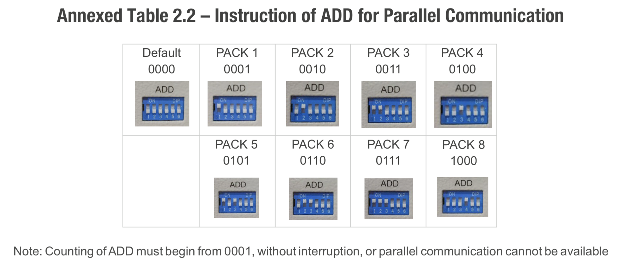
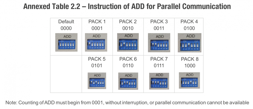
Just to be absolutely sure, your first battery which is connected to the inverter is configured according to PACK 1 below and your second battery which is connected only to the first battery is configured according to PACK 2, right?
-
Did you try to set the DIP switches (left to right) to: 100000 (master, connected to the inverter) 010000 (slave, second battery)
-
Here you go. BMS-ND_Gyro-V1.1.634-32-13.zip
-
Looks like it may well be a Tian Power BMS! I am really impressed with how you identity multiple BMS types I tried using Lithium protocol 9 and was really surprised when I saw the real SOC coming through on the Deye inverter! I could almost not believe it. However, the battery temperature was reported as 330℃, so obviously the data was not all correct. Whilst I was looking at the other values, BOOM, lights out, wife unhappy again! Yeah I shouldn't have tried this again during a grid outage. I didn't learn my lesson the first time. The inverter disconnected from the battery and reported error F51 (W phase grid current DC component over current). Apparently this error has never happened so far according to the Deye manual. It took me a while to switch settings back to not use Lithium mode at all, for the inverter to reconnect to the battery and for me to calm the wife. I mean come on, why won't she understand that getting BMS comms working is crucial? 🤔 Anyway, I think I'm done testing for the night. This was progress at least. My conclusion is that Deye/Sunsynk might not support Narada using Tian Power BMS with Lithium mode 16. And yes, don't set it to Lithium mode 9 during a grid outage
-
Hi @Jay-Dee, what do you do to reboot the inverter?
-
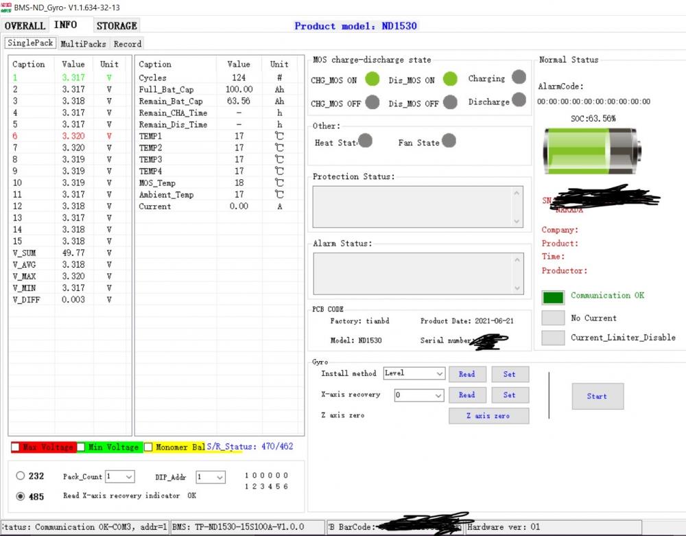
So I have some good news and semi bad news. The good news is that Solar Assistant is able to connect to my Narada 48NPFC100 battery BMS and read the values. I noticed that the real SOC read from the BMS can be quite different from what the inverter “estimates” it is - there can be a variance of around 15%! This is why it is crucial to get BMS comms working on the inverter. Further good news is that I also managed to get hold of the correct software for communicating with the BMS. I am not sure whether this is Shinwa or not, but here is a screenshot: Baud rate was 9600 and I can confirm all of the usual parameters are correct, eg stop bits, parity, etc. The pins I used were 2 and 3 on the RS485 port (both RS485 ports work). I do think that pins 2 and 3 on the one hand and 7 and 6 on the other are just mirrored on the port. The bad news is that I still cannot get my Deye 5kW inverter to communicate with the battery using the BMS485 port and Lithium mode 16. At least there is hope though. Either I am overlooking something or Deye simply does not support this BMS (yet). I have crimped yet another cable and using inverter pins 2,1 to battery pins 2,3, and used my network cable tester to verify. I am not using GND. I do reset the battery using the reset switch every time I attempt a new combination (I did this during load shedding at night and caused an outage at my home, unhappy wife, etc). I am still hopeful that I can get this to work and will send Deye support the above details. If anyone else has gotten their Deye inverter to speak to their Narada battery with the BMS in the above screenshot (TP-ND1530), please let me know!
-
Solar Assistant trial obtained, thanks to Pierre I will report back on findings.
-
Thank you for the kind offer but I am in the JHB area, so quite far away. That is a very smart way of reverse engineering the USB to RS485 cable without ruining it! I thought of buying one of those cables just to verify which PINs it uses for the A/B/GND signals, but you have answered this now. So there is nothing special about this cable? I do have a spare USB to RS485 converter that I can use to test this. I see the Solar Assistant Narada RS485 cables (and software) have been updated “to support the latest Narada batteries released in Q2 2022” - I wonder if the PINs are any different. In any event, I thought of requesting a trial of Solar Assistant (if they do trials) just to see if it is able to read my battery. That would then confirm if the battery firmware is fine or not, like you say.
-
You should get the same behaviour when monitoring via the BMS485 or RS232 ports. I have used them interchangeably - the same set of registers are read via either port so functionality should be equivalent. But perhaps the issue is specific to ICM? My issue is that the inverter does not speak to the battery with Lithium mode 16 no matter what combination I try. I’ve tried (arranged according to A/B RS485 signals): Inverter pins 2,1 to battery pins 2,3 Inverter pins 2,1 to battery pins 7,6 Inverter pins 7,8 to battery pins 2,3 Inverter pins 7,8 to battery pins 7,6 All of the above should be valid combinations because pins 2 & 7 and 1 & 8 are joined on the inverter BMS485 port, and the same should apply to the Narada battery pins 2 & 7 and 3 & 6 on the battery side. Deye inverter: Narada battery: I have a single battery and have dried DIP switch positions 000000 and 100000. Your post made me check the inverter 2,1 to battery 7,6 combo again and I almost kicked myself when I saw that the network cable tester reported that one of the pin combos was not working. I re-crimped the cable several times until I realized that the “remote” part of the network cable tester was faulty and when I tested the cable on the main cable tester unit only, it did check out. So the cable is good and there is still no BMS comms. My suspicion is that it is the BMS on the battery side that either needs a firmware update (not sure where to request this), or it is a BMS that Deye didn’t test Lithium mode 16 on, or the BMS is simply faulty/non-responsive to the queries from the inverter. This is why I need to pin down which BMS is in the battery (without opening it up hopefully) and trying to read values directly from the battery via an RS485 to USB adapter with the correct software (which I don’t know where to get :D). The software that @zivva posted allowed me to read the date/time from the BMS but not the SOC, SOH, etc. So that is where things stand at the moment.


-
Yes, that would be ideal, inverter to battery BMS comms, inverter live monitoring and data logger, all connected at the same time. Unfortunately us Narada battery owners might need to settle for two out of three because the battery doesn't do CAN. Personally I would drop the data logger in a heartbeat if I were to get BMS comms going on the BMS 485 port and only connect it when needing to do the odd firmware update. Regarding the RS485 port, it seems to be present only on the 5kW models with that label and is for energy meter comms. On the 8kW model it is called Meter_CON. Who knows whether it would ever support Modbus queries the way we want it to. 5kW Deye: 8kW Deye A different avenue that I would like to explore given time (which is scarce) is using the CAN port of the inverter to communicate to the Narada battery by converting the CAN bus comms to what the Narada battery expects by using a Raspberry PI. I have an RS485 CAN HAT which can do both RS485 and CAN bus. The idea would be for the PI to act like a CAN-compatible battery to the inverter and it would in turn speak to the battery via RS485. I think it would be something similar to this. At this point though it is purely speculation on my part that it would work for the Deye/Sunsynk and Narada battery combo.


-
So both Solar Assistant and ICM should work with the BMS485 port for monitoring the inverter. The RS485 port (bottom right) doesn't work for that purpose or at least the pins are not known. I have a raspberry PI connected to the BMS485 port of my inverter and it works well. However, if I change the lithium mode from 0 to 16, then the BMS485 port changes its behaviour and does not return valid modbus responses when queried. So the predicament here is if eventually I do get BMS comms working from the inverter to the Narada battery, I will lose the BMS485 port to BMS comms, which will mean I need to use the RS232 port for monitoring (which works too) and then I lose the data logger. Or what got me excited from the previous response from Deye was that potentially BMS comms to the Narada battery can be achieved via the BMS CAN port of the inverter, but that is likely a typo as previously mentioned.
-
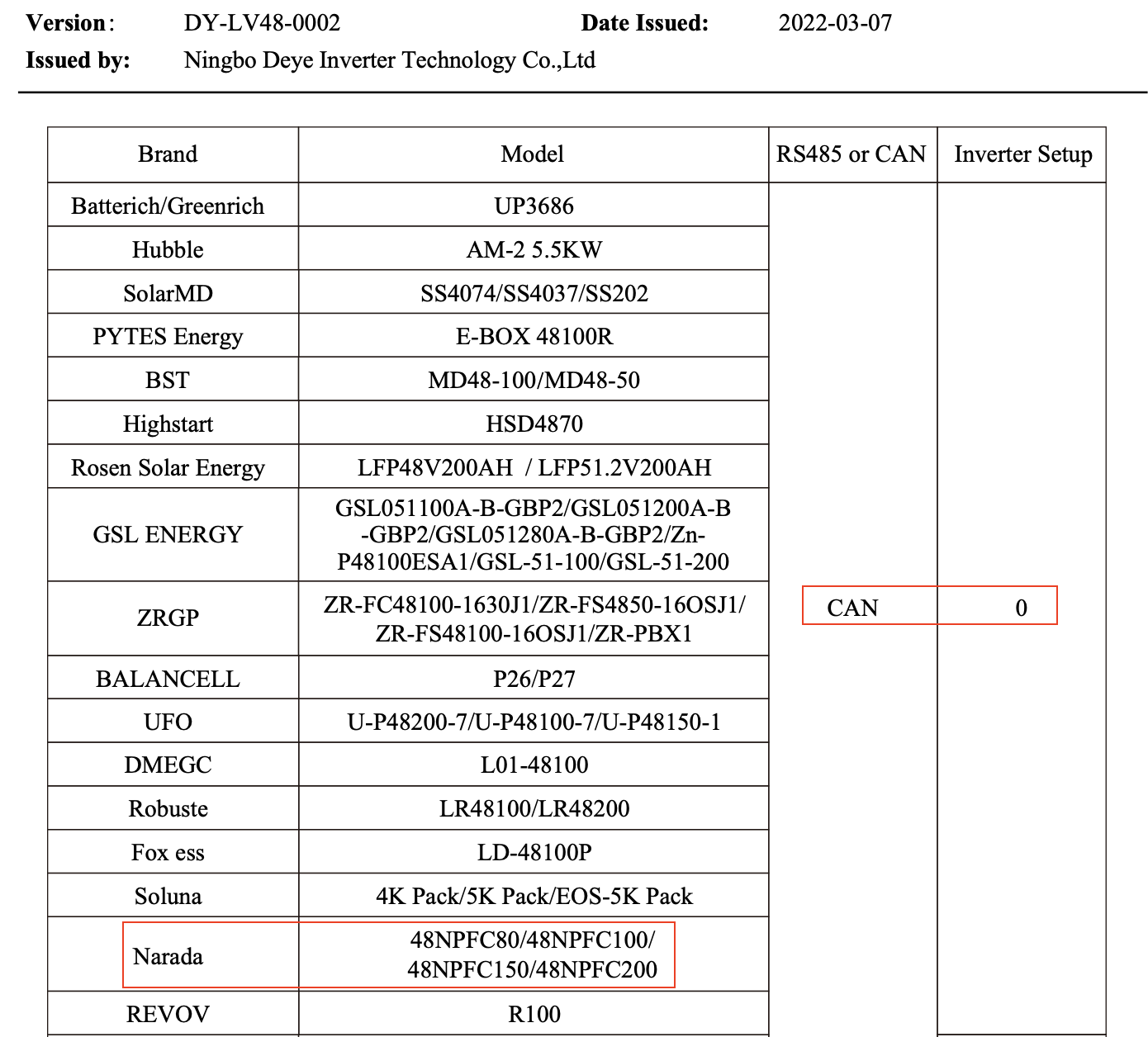
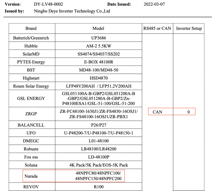
Yeah I thought it might be a typo but deep down I hoped it would work because lithium mode 16 on the inverter causes me to lose the ability to monitor the inverter via RS485. I still haven’t gotten my Narada 48NPFC100 to work with the inverter RS485 port and lithium mode 16. I downloaded the Shinwa software you attached earlier and was able to read the BMS time but nothing else, so I think I have a BMS from a different manufacturer, but not sure how to find out without opening the battery and losing the warranty.I've been in contact with Deye and have received new information. The connection to Narada uses the CAN port now apparently with the latest firmware on the inverter, please see attached. I have been unable to get the info on which Narada pins should be connected to the inverter CAN H/L pins despite asking several times. 最新-Deye Approved Battery list(DY-LV48-0002)(1)..pdf
 The problem with the Deye and Narada battery combination is that I need to set the Lithium mode to 16, which causes the BMS RS485 port to change its behaviour - I can no longer receive a valid Modbus response if I try to monitor via that port. I assume the behaviour is changed to allow the inverter to speak "Narada".Has anyone been able to monitor the inverter via the BMS CAN port instead of the BMS RS485 port? I am hoping to establish BMS comms between my Deye and Narada battery which will use up the BMS RS485 port (Narada doesn't do CAN), so I will lose monitoring capability unless I disconnect the data logger from the RS232 port and use that instead for monitoring. I read somewhere in this thread from @Sc00bs and @kellerza that using the CAN port might be possible. Have you succeeded in doing this, i.e. either finding an RS485 signal on the CAN port (if there is one), or monitoring via CANBUS? I got myself an RS485 CAN HAT and have hooked up A/B on the HAT to the BMS RS485 port on the inverter and that works well, but as mentioned above I may lose the port if I want proper BMS comms between the inverter and battery. I have also at the same time, as an experiment, hooked up the H/L on the HAT to the CAN port H/L pins (4/5) on the Inverter but realised this might not work with Modbus? How would one even begin monitoring via CANBUS, or is that not possible at all?I tried this as like you said, it wouldn’t hurt, but unfortunately it didn’t work. Ok I tried this again and it still didn’t work. Inverter BMS RS485 7/8 to battery 2/3. I had the DIP switch set to 1 and used the MCB as well as the reset button for good measure. I also tried both RS485 ports on the battery side as I think in your prior pictures you had the inverter connected to the rightmost RS485 port, but neither the left nor right RS485 port worked. After using up almost another bag of RJ45 connectors, I give up. The one thing that I think I will try is to order a RS485 to USB converter and see if I can communicate with the battery via USB. If this works and I confirm the RS485 pins that work on the battery, surely that would mean that the inverter should be able to connect to the same pins?