


wael_fathe
Members
-
Joined
-
Last visited
Everything posted by wael_fathe
-
i will sure brush up my ac theory to understand this ...i hope also if you prodivde a picture so that i can follow up with your complicated yet precise explanation -------------------------------- so the very brief of your explanations is that once 2 sourse shift in phase by 1 degree with an L BETWEEN THEM "there will be voltage , small one across the L AND since current always is not in phase with voltage and have 90 degree of defrence that current how ever is actually in phase with the voltage of one of the 2 sources " AND thus power can flow form that source once ac come in and the inverter synchronize its output with the coming input ac suppose the user choose that inverter provides ac output for loads we get an inverter that does provides electricty and charges the battery in the same time if the inverter wants to suck as in it changes phase a bit if its wants to spits its own ac it also changes the phase a bit in tiny seconds the same igbts that were rectify ac to create dc they may switch the dc high bus across the transformer and create low voltage ac for themosfets to rectify it and create the dc charging for battery wow wow amazing >>>have i got it mr colomb pleae tell me if what my ideas in mind are right thanks -------------------------------
-
i have no problem with my mosfet i have problem with output igbts for h bridge i got 100 pces from china they lack the diodes , ------------ That's too easy; the DSP arranges the phase so that power flows from the DC bus towards the load. If the load increases or decreases by 1 kW, that's no problem, the grid instantaneously supplies the difference. That's Kirchoff's law, so it's instantaneous, and the DSP doesn't even have to make any changes, just keep that 2 kW chugging out to the load. THIS was your reply to britshgreen racing sorry to re-asking... but if the solar dc fed to the high dc bus and turned into ac 220ac and even maybe get synched with the utility ac interms of amplitude frequency and phase now both (solar generated ac ) utility genertaed ac in complete synch how cpu can source power from one source and omit the other or how can source a load with controlled power mixing say 20 percent from solar 80 from utilty to me if all waveforms are in complete synch there we cant instruct one to provide and other not 2 they should alwyas do 50percent power for the load ?so i guess that 1200vdc 30a high speed diode will be more than suffeinct but will they be heating the diodes not need to be heat sinked i guess ? back in old good days of crt repair horizontal output transistor come in 2 flavors one with diode bult in one wit out the one without have an external diode i wonder if we can do the same for inverters@Coulomb few important quesions mr colombs hope y answer them will the igbt buck stuck on when inverter works because it have no rule as its only rule is in charging cycle or they some how rely on the bult in diode to "pass" the igbt ? how can we ramp up the inverter slowly increasing the voltages acorss the 450 bus voltage when it is already ramped up to 400vdc by the soft start circuit ? so do you think there is not inverter soft start due to the soft start circuit? today i recived 100 pces igbt 40q60 alas they have no built in diode big lose for me ...i will try to fix this by installing external diode will it work?what is diode specs i should use? how can i turn 2 wire fan to 3 wire fan or at least let the cpu accept 2 wired fan because we inject speed report wire fake one ofcourse ,,,,,we let cpu think that fan is doing good all the time ? can 4 wired fan be used instead of 3 we just have to ignore the wire that controls the speed and leave the one that reports the speed?i am happy you now explain to me why diode on mppt and igbt failed lets recap all story for new comers so that my reply to you be understandable to others inverter come in with all igbts goood all fets bad i removed all fets and power it up i gooterror 09 it was ok to get 09 since all fets out of circuit but for me it was not ok why i should not get any momentry pulses and tried to follow why cpu not turn the mosfets by sending signal and failed i then removed all igbts and turn the device on i get momentary primary side pulsesand error 52 ok now its better however when i fited all fets i get error 09 again end up with inverter that is all ok and i have no output i removed the fets again now since i tested all things 12vdc minus 12 5 5.6vdc 18.vdc coplers resistor diode in priamry and seocndery i decided to change the 500vdc caps i was lazy so i told my self why not to seperate the inveryer board from mppt which might seperate the bad cap and that was bad idea since soft start is in the mppt board , and will work indefinatley , since cpu turn it on and with no voltage on the bus of the inverter the soft start will incvrease the voltage so high and blow mppt diode and mppt igbt probably because the measuring is done across the inverter 500vdc cap not the mppt caps after i replaced all bad diode in mppt and igbt and repalced the cap, and soldered all fets the inverter works nicely mission done بfirst i replaced the cap with new 400vdc for testing once the device work fine i get large 450 vdc 470 mf and replaced both large caps the inverter works fine since then thanks colom for showing me why actually the diode and the igbt in the mppt failedThat's pretty weird. All I can think of is that the MPPT input capacitors retained some charge, and there was enough energy stored in them to destroy the boost transistor and diode when the MPPT connected and there was no load on the MPPT, so nowhere for the inductor energy to go. Also, the DSP would be using its own bus measurement to decide how much boost the MPPT needs, and since it saw no bus voltage rise, it commanded more and more boost. the soft start circuit does exist on the mppt board conifirmed ...maybe when i seperate the cables there was not enough capacitance to mooth the resulting bus voltage a nd thus that damaged the booost diode and booost transistor igbt>? could be a possibility?there is no slight doubt thhat they are bad as the moment i changed them the unit works ok the 400 units were just temporary fix thanks but the fact that they not go bad is just according to you own experiencethey appear ok ,,,as i checked all things and as i removed all fets and igbts still cpu only for a fraction of second does give the fet and active rectifiers signal drive i suspscted the caps fail the cpu test when i replace them the unit work ok but i have small question the newly installed caps are 400 volt ....will they endure the orginal one were rated 500 another question mppt board does charge those caps the man install 6 seiies solar panels around 250 vdc voc what voltage you would expect across the caps once the mppt works and try to charge them i imagine more than 400? as mppt will try and boost the 250 to 400vdc so that h bridge can turn it to 220vac - last queston during the repair i sus[ected one 500 cap is bad insteaad of replacing them i decided to remove the b+ bus wire that connect the mppt board to the inverter board and when i turn on the inverter fried 2 power igbt and boost diode those parts are some what connected to the bus but what they would short like that ?? they are not in switcing state ? they are for mppt and i not connect the inverter to sun or any thing its just 50vdc power supply?thanks for taking the time i actuallly followed the wrong repair path the problem was in soft start and a case of almost shorted cap that alert the cpu to send 09 error with the caps repaired all things work oktrue that what happen i followed the unlogical path .............could colomb give us the checking process order i know the inverer checked for fan first what else it does if we know the order we know how to trouble shootthanks colomb i solved the problem i took the wrong repair path all the time asking why the cpu not turn the dc to dc the entire inverter seems ok except the primary side fets the cpu refused to turn on because there was fault in secondery caps when i removed all fets and turned on error 9 appear when i removed all igbts and fets error 52 appear and another good thing ,,,cpu tutn the dc to dc for one second this tells me that sg 25xx working cpu boaard ok and some thing else is wrong i test all things nothing bad as last dispaired attempt i changed the caps and fitted new mosfets when i turn the device i was shocked that the device not make arror sound the screen was turned all the way down when i looked at it i saw a 230vac so lets anylise why that happend the device come in for me to repair with good igbts in secondery and tottally destroied mosfets i failed to thing properly it was quite logical to suspect the caps right a way what could blow mosfets if no bad commponent in secondery side shorted since all parts in secondery ok the caps are prime suspect they pulled large current and failed the soft start to work may be they eventually go almost shorted and stressed the dc to dc to blow the mosfets i failed to analyse the failure and lost 5 days looking for trouble that does not exist thankshello colomb ..it is getting interesting here qmax5000 watt i knew the secondery side igbt circuit assumed to be good all fets in primary are out of circuit i decided to short the sg3525 optical copler i did it and i get a nice square wave so sg3525 is good but why the cpu not send on command ,,,,,i tested across the diode side of the copler one pin was tied to 12vdc the bottom one should be dragged down to ground sg35xx to work but i was shocked with 14vdc at the bottom, leg of the diode side of the copler in short. the copler is reverse biased by the cpu board ,, the cpu wait for 30 second then issue 09 error and in this 30 second it never turn on the sg3525 ...i changed the uln2003 driver ic with used one but it is the same no improvment still no square signal can you guide me a bit ,,,,,what else can prevent the cpu .....i even thought that uln2003 have no ground connection reaching but find it grounded should i do factory reset? should i replace un2003 again?..i have 1.5k with same board should i test it with it? should i clean the cpu with solution may be some dirt stuck on legs? i tested the 3.3 5vdc 12+ -12 all good i totally lostthe problem is that many people in this and other forum report it to be open circuit when there is primary fet short it seems to do n active or partly active role ....but it looks so passive in the edge of the boardhttps://ibb.co/D5QZ3bS the link has big picture i encircle the resistors in red circile can you guess thier function i follow the circuit it seems like this 2 resistor parrlell ...one side of them goes to ground other goes to ceramic cap which has its other end to battery positive the knot where the cermic cap and resistors tied goes to 100mf cap in main smps probably input i draw simple schem it seems boostrap to kick start some thing as voltage apppear on resistors only at the start soon ceramic take over s c
 sorry for interuption of whatever the subject you great guys are discussing today got qmax 5 k primary side fet shorted all resistors ok except one open 100 ohm and 2 other burned beyond recognition the rsistors is R93 R105 SMALL not 1206 size ...more smaller sg3525 produce no square wave i wonder if they the cause? ..what those resistors do?\ are they parrallell cant know tracks are damaged? let me fisrt replace those then i trouble shoot more the shot from vmii series service manual....they not show value
 this ic i fnd near tl494 in normal inverter not solar one manufacture usually use lm358 this one is not 358 can you guess number out of few remaining letters?
 you have cured my eyes sir , in the rev 01 threr was a mistake and no matter how much time i spend looking at the schmetic i cant translate it , now it is understanable thanksHI @Coulomb I HAVE list of some vital question hope you can satisfy my curiosity --------------------- 1-from relay configuration of solar inverters i can see that ac grid is some what conncted to outut of the inverter this should explode the igbts so i assume that synchronization process happen between ac grid and ac inverter? ------------------------- 2- too many sps configuration but mainly it can be like that bttery operated smps that produce 160vdc which can be diode ored with 300vdc of ac grid to fed both main sps 12-12+5 and soft start or in the second configuration ac operated sps that produce 160vdc and battery voltage both can be diode ored to spftstart and mains smps 5+12-12?? ---------------------- 3- the soft start circuit function is to fully charge caps at 370 or just partially?? how error 09 can be generated low bus voltage or no buss voltage or good bus voltage that have not reached the target in the specified time!? ----------------------- 4- in the shot uploaded some windings of the driver are not refrenced to the mosfet's source which they drive ? ------------------------ 5- i read in a book there are igbts that used for zero current switching? other say there is sorts of active snubber circuits in solar inverters ? is that true? ---------------------- -6 some manual says some thing about discharge ciruit is that same as the buck igbts which mainly used for controling charging process or there is another discharge circuit ? -----------------------------------
 this is scope picture go on and download all repair files from here you will enjoy them they are numbered 1.2.3.4 etc etc they have comments on them you can follow the entire repair story just by folliwing them https://www.mediafire.com/file/axldufan39ufoqg/repair+story.rar/file
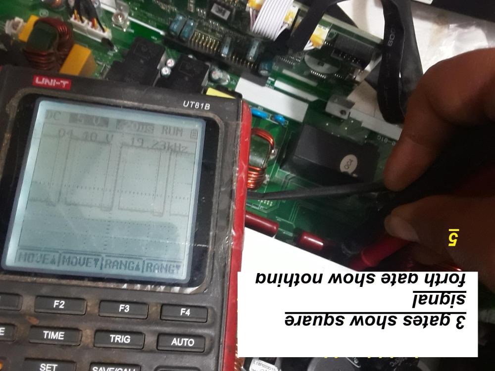 please download rar it contains alot of repair pictureshello people first i would like to give special thanks to mr colombos and all people in this great forum for thier support and togetherness today i carry to you all guy success story so please listen qmax 24vdc 3000 watt come in for repair the problem was 09 error i opened the inverter and find the previous techncian have replaced all h-bridge and rectifer igbts by bad quality igbts the primary fets and thier drive circuits cheked ok and i also find few burned zeners and reisstors in recctifier igbts gate cicruits i assume that the inverter first come in with onlyhbridge igbts problem after technician replace all igbts with bad qualty one , he introduced another failure , since all rectfier igbts went bad i started by cleaning and replacing eevery bad zener diode reisstor in rectifier igbt gate circuits , after i finished i checked the h bridge igbts they seems all fine i installed new igbts for the rectifier igbts and fired the units on error 09 appaer again and one igbt in the h-bridge shorted i felts that i was too hasty , i should have checked the busvoltage dc and the pulse drive for the hbridge igbts before i turn the device on so i desoldered the h-bridge igbts trun on device and tested the bus, it was normal at 370vdc also the drive gate was ok square wave , it stays for about 3 seconds then the device shutdown and report 53 error but i noticed that one drive is missing i shitdown device and trace back to find 47 ohm resistor opened i solder new 47 ohm in fired the unit again checked the wave forms they all check ok , i have feeling that with new igbts it should work fine true enough i installed k50h60 and turn the device on it all worked fine i even lload the qmax 3k inverter with 60w lamps it glowed nicely i cant believe i did it the gates of the rectifer igbts have lots of bad reistors and zener i did it i did it i am happy ! about 16 picture is loaded for the repair story you can easily download the picture to see how i did it each picture has number follow the numbers from 1 to 16 to see how i progressivly repair the inverter .https://www.mediafire.com/file/axldufan39ufoqg/repair+story.rar/fileIf you're referring to the battery terminals (which could be 12 V, 24 V, or 48 V), then yes, you need all those protections. But there is no need to connect anything to the battery terminals for this testing.EER I dont get this i have 2 methods one with connecting the battery one without connecting the battery the " one without" , we use instead a dual power supply 12+- but you told me for the second method also dont connect any thing to battery terminals! the second method invlolves unsolder fets and rect igbts connect supply dc input 24vdc diable cpu ,drag sd pin 3525 to logic low , power on the main sps by turning on the power buttom scope for wave forms ! so it does involve connecting the power supply ! thanksin the inverters that use mosfet output, i have replaced many times 47n60 with irf460 and vice versa with out any heat issues . if mr combos agree mosfet is more friendly when it comes to replacement than igbtso with dual supply 12-+ and with cpu board diabled or removed and with out bother turn the power bottom on and with out bother remove fets out or remove igbts out we can go on short method and test for drive in both primary fet and secondery igbt(rectifiers) ?? ------------------------------------------------------ but with the 12vdc or24(according to inverter's dc input ) plugged in fear factor is in ! we must make sure cpu is disabled all pri fet removed all rect igbt removed caps at +hv bus have to be checked for high voltages and only then ....igbt and fet can be tested for square wave? 2 diffrent routes for the detective to find the cuplrit wit each one offering diffrent degrees of easiness vs riskness


