


wael_fathe
Members
-
Joined
-
Last visited
Everything posted by wael_fathe
-
hello @Coulomb am stuck with a unit that have only 2 sps one is battery sps 12+ 12- 5vdc or mains sps and the other is the soft start the unit is 24vdc and the sps turned off due to short in the 2sa1020 drive npn even after replacement 1020npn the 12-125 sps is dead i reached stage where i have to replace the transofrmer as i tested all othger components ...can i get this transformer from other units that is not 24vdc my unit's main sps uses 24 from battery directly via steering diode the donor unit is 48vdc worest its mains sps transformer is not fed from battery but rather from battery sps that generate around 100to 120vdc they look physically the same am not sure what to do one x trasnsormer fed from 100 on fed from 24 both produce the same vdc and have same look may be they the same if the maker change the frequency of operation to compensate for different in the input dc???
-
for your information this model have great tendency for its output capacitors to be completely open with only 10mf instead of 470mf //....micro farad i mean by the "m"
-
thanks i checked both orginal and the one i installed rated 561 hope with this thy match 14d561k...burned Tvr20561 replacment


-
the pv positive input is to one varistor the pv minus input is tied to other varistor the 2 left alone ends of the 2 varistors are tied to ground actually you commented that the pv input to ground are wierd yes they are wired ...but i didnt say that i find a part have 20k560 on it and installled it the first 20 is all about the diameter the most importnat number is the 560 ...thanks for help mr coulomb
-
Helllo got 10 qmax inverters with cracked varistors number 14k561 Cant find any in local market but 14k471 Will they work ..? They exist in input sction of mppt 2 varistors The first end of the first variator is to pv minus The first pin pin of the second variator is to pv plus The 2 remaining pins of both variators are tied together and to chasis ground Any idea about replacemnts @Coulomb
-
My initial guess is bad output cap...as ripple increase due to largeload....cap fail to supress them...one spike registered as high voltage....very logical ... This model is for a company...installation company i repaired 10 pces they all ok...however this one only have problem ...i also suspect the input fets...as all first 9 pces all repaired with hy3712 super solid chinrse fet... But this last is mixture of hy3712..and 85h160 fet that i survived from bad inverter So i guess there sort of unbalance creating the wavform in the primary due to may be diffeent threshold on voltage Just a guess based on practical clue...with9 pcea working and one not
-
Uk solar inverter 6k clone...giving me 08error .afterexceeding 2k ...with only batterymode ...no utility...no solar... What is the possibilities of the failure @Coulomb @BritishRacingGreen
-
Oh Your guess is logical...and that what i think...but sako inverter manual refers mysteriously that drive of dc to ac is the cause of 08.....how that can be is beyond my brain @Coulomb probably know Just write sako error 08 in google and file will pop up in serach results
-
Updates First the sg get fairly hot and that is normal ...at working fans. Are directly facing sg and the temp never get sensed well using ur finger When we do columb trick of shorting copluer u19 no fan will spin and that is where ur finger sense the temp Another update ...use columb trick when ever possible...even if all component test good u will burn things ..here is. A case .. Where one leaky diode test good in forward...and taste some leakage of 2.2in diode mode...i thought it be some partallel component But once diode out of board i taste in both direction one gave 0.6 ok in other it gave 2.2. Bad ...good diode never test in both direction My testing skill failed...once i apply trick i notic on set of mosfets give this cut waveform...which led me to test all components related to thses fet extensively and precisly and out of board Columb trick is Day saver


-
Yesterday i. Was testing an inverter primary side mosfets waveform using scope...using columb trick of u19shorting......i notice that sg2535 is having some heat...is that normal Like if left finger too long for minute...its becomes hot to touch any more Power supply drawsnormal 0.15amp Any guess @Coulomb @BritishRacingGreen
-
solved customer reverse fan and the extra cooling convinced the marginal tempreture sensor to stop fault 02 its sure an mppt sensor as the inverter work endlessly fine with out solar ...customer have left his inverter outside the cabint i opened it and saw one of the worest capacitor degradation process in my life caps back to its orgins just a paper roll!
-
today i repaired inverter with error 52 with only replacement of sg25xx ic logical repair as bad ic wont send enable dc-dc stage to work no dc to dc = 52 no dc to dc due to shorted high volatge bus = 09
-
Tabular battery from india i think.. The man. Left the. Unit working outside and in harsh cirumstances So sensor could be bad I not know how to watch the inverter using software ..but try to google the method
-
On sunpal ..inverter 5k ..customer showed me error 02.. The error is due to over tempreture in mppt heat sink..i proved it cause when customer turned off mppt And use the inverter on batteries it work ok He not have ac from utility...its a cottage in the desert. No way Wierd enough the customer told me that error occur when battery is full while no or little load . In the video he sent i also noticed that mppt draws 1k from sun while battery is almost 53vdc that huge draw in a close to full battery Eaither bad tempreture sensor Or bad batteries that draw lot of current loading the mppt ..just i wonder why cpu throw a 02 on battery error @Coulomb @BritishRacingGreento
-
I totally destroyed the timing(soldering iron slip) capacitor and replacedi t with wrong value i base my decision on getting same color same size that was mistake After i get right value i removed the previously installed cap and put new one with the precise value All in order... the unit worked
-
The soft start exist in mppt...typical of this clones..chinese manual full of mistakes..i wonder how they raise in civilization with horrific grammer and typos ...but they did and we are fixing thier units heheh
-
٩@Coulomb @BritishRacingGreen I did fixed it...the fault orginally was bad connection unit some times work some times not...but once fixed I introduced another fault by removing small capacitor nearby uc3845..i did replace that cap but with the wrong value.which altered the workibg frequency of the chip Which chnaged the dc output voltage to very low.. With the right value cap ..the main sps produce 8vdc 12vdc and minus 12vdc once i put everything back the unit work I hope gain entery link at other forum runned by mr columb Under the address "clone 24vdc sunon pro..battery sps and main sps Could also be applied to many clones" I hope the schematic i got from manufacturer get to many technicians out there..... Its not easy get them...they gave it to me to fix thier unit cause the unit under warranty if i failed they pay the customer back full refund So they support me in whatapp chat Better than paying customer back

-
I think i am.close to find the problem of the low output in main sps...while changing the uc3845 i knocked timing capacitor...which changed the working frequency..which will effect the dc voltage output , look at the feequncy..i forced the ic the produce waveform just fed 12vdc to pin7 ground to sensing resistor since it is always hooked to ground...got this wave form ...that is bad ..it cant be 1khz no way @Coulomb @BritishRacingGreen


-
Good news today.. The company gave me full schematic for both battery and mains sps to help fix dead mains sps I will ofcourse put them for benfit of good people ... battery sps was really normal output of 150vdc...no doubt now .. By the way this is the most clone design i have met..if well understood will open the gate for understanding alot of other makes and models @Coulomb @BritishRacingGreen


-
Congratulations bro...
-
Congratulations bro...togetherness is key for technicians to survive in modern day hostile environment ..hostile because manufacturer are not willing to gave any schematics and real manuals and guides... congrats bro again
-
Excited to do it ...fake12vdc at out cap will fool ic ...we.will expext changing pwm if change vdc at output cap..hmmm .interesting Today an engineer from sakko sent me screenshot of feedback circuit of sunon pro 3k 24vdc solar inverter as i knocked down resistor r105 ..so he sent shot ....how close that to voltronics...hoping for the entire smps and battery sps to be sent

-
Mr colomb...easun has not seperate sps for 150vdc....am refering to sun on pro solar inverter from sakko manufacturer ...still in negotiations with company the promise to provide help and schematics for thier 3 k new yet dead inverter once they provide it we will discuss it here
-
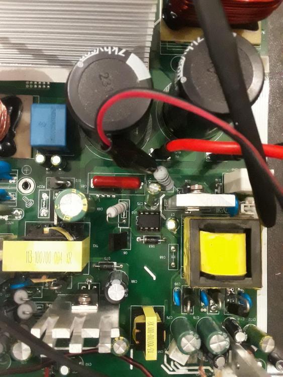
c69 is rated 200vdc green one ...i actually tested one good working clone inverter and it gave me 120vdc input so it seems 150vdc is not that far and i assume the system normally give 120 in some clone and 150 in others (left smps in picture) source for 150 to the (right smps in picture) whcih xt for main smps which should work and produce all good vdc voltage 5 12 -12 but that never happen there is one more strange thing about those clone inverters even if both smps are good they work for about 3 sconds produce 120vdc ...-12 +12 5 then they shutdown only when the control board inserted , at that only case the work fine ,and continue witout a shutdown by the way clone that give me 120 output is 48vdc the one that give me 150 is 24vdc
-
i wnated to delete this reply i could not


