wael_fathe
Members
-
Joined
-
Last visited
Everything posted by wael_fathe
-
nice trick thanks never before know any dynamic test for feedback such as yours thanks again i do have 2 power supply will try to do it ...much easier is to fed the transofrmer with 120vac at high frequency..and see what the transofrmer gives at the outputs ..i higly suspect the transofrmer
-
i have bob paker ring tester..i used it it gave me 4 rings it is a marginal result could be good could be bad the device have 8 led indicator it seems 8 led lit means fine 4 led marginal and probably fine above 4 is fine less than or equal 3 is bad ... i closed the unit down ...in despair..my last try in thought about injecting a forced 13vdc to pin 7 vcc of the uc3845b using or-diode and observe the output....alas the output gave me 4vdc in what should be 12vdc output some thing is bad ,,,and it is not ... a feedback is i knocked a resistor in feedback cirucuit out and stilll get the same result open loop failure it have to be a transformer about your suggestion of feeding in 20khz i got a nice idea how about stealing some ac high frequency/from another inverter feed that in ... 200vac...f= 20khz and see what sort of junk output i am going to get?!
-
this design is normally produce 150vdc input to main sps... its clone...but the outputs too low ... yes pin 7 is 8.2vdc uc3845b done all the doable time to change the transformer...any ideas to test it؟
-
nice...smps discussionBritishRacingGreen i was totally defeated with dead smps of a clone 6k solar inverter the main smps is fed by battery sps that produce 150vdc input ....the 150vdc comes in...but no12...no5vdc...no-12 dead replaced us3845 ...no use tested vcc.is 8.2vdc tested diodes ok no output short ..the ic is ok i fed 8.5vdc without even powering the inverter and got square signal at pin 6 and5vdc at refrence pin i tried to tweAk start up circuit by reducing some resistors to boost vcc...no use vcc still 8.2vdc i notice with a scope the ic produce some pulses at start up but no output[though pin 8 .never give 5vdc) ...actually there was around 2vdc at output at startup phase...then it all collapse i run out of ideas replaced coopler and tl431 no use i lastly suspected smps transformer...can i test it with variac...any other ideas..or shorted aux winding.. repaired many but this one exceeded my skills
-
this qmax solar inverter is strangely designed first it is compact with some vertical boards for ac ignt output drivers and vertical board for sps and soft start sps second with the ac output igbts removed it should give error 53 soFtstarting ac failed with output ac igbts removed it gave error 58 which is low ac output ac suddenly raise to 230 no raising in soft start fashion the breif is that some units have fewer codes available(no error53 in this one) and fewer fucntions missing(ac not raise gradually) they ALSO INSANELY INSTALL 6 fets there 10 places but they ommit 4 of them however after i fix it i install the missing fets along with thier missing drive componenets

-
As short as possible for new comers ...its eaither way The oring happens at the battery side where all 3 sps(mppt sps..ac sps..main sps) ored there so that they operate main sps without on command Though that bit strange as it seems that main sps should always work yet its not if on_off switch in off position...maybe the onnoff switch is used to cut dc for the mains sps whilhe other sps are fed directly with no swicths or any restrictions Or 3 sps (battery sps .ac sps..main sps)..this one i have seen alot in clone models...battery sps is stupid sps that produce 120vdc or so to operate the main sps oring happens there at the output of the battery sps where mppt not need an sps they derive some volt from working controller or panels battery sps work by main switch...mppt and ac sps inject power directly at battery sps forcing main sps to work ....
-
Great explanations the entire process is natural ...only after h bridge ac phase have to be adjusted to suck utility ac in if the battery low and bus high or to spit ac out if battery high bus is low
-
How much voltage drop is legal after the application of this load ...from 12- to-11.5 is still good?
-
its abit warmer than usual...i gave back to customer it works fine for 10 days..so far so good
-
Hello ...what is the normal tempreture of output igbts heat sink I can sense it with my hand with 100 wattt load its a bit high tempreture ...since i cant tell how much the tempreture all i cab say it is bit higher than a warm heat sink...the output coil is however cold...strange since all ones i repaired coils is more heated than heat sink can any one answer the inverter is 5k qmax clone probably
-
craziness what if we choose solar first and utility last....forr loads but then we contradict this when we choose utility as priority charger we end up providing loads with utility ...if loads are heavy ...each time solar fail to sustain all loads battery will bee invited when batttery drops utility will charge it factory should make thier manuals comprehensive and cover how loads priority acts with different charging options also i have question regarding 450voc 3k units most of them 4500 watt solar 24vdc while controller 100amp but 100amp multplied in 24 is only 2400 watt how can controller supports a wattage that if produced will exceedi its rated current?

-
thanks for your comprehensive answer ...alas i ordered 100pces 3150 and 100 t350...if i got this piece of information before i would have made my order all in t350
-
can i replace bad copler for3150 with t250? will it work ? the "suspected " bad copler have 30k between its 18vdc pin and 5 vdc pin is it normal reading ? @Coulomb
-
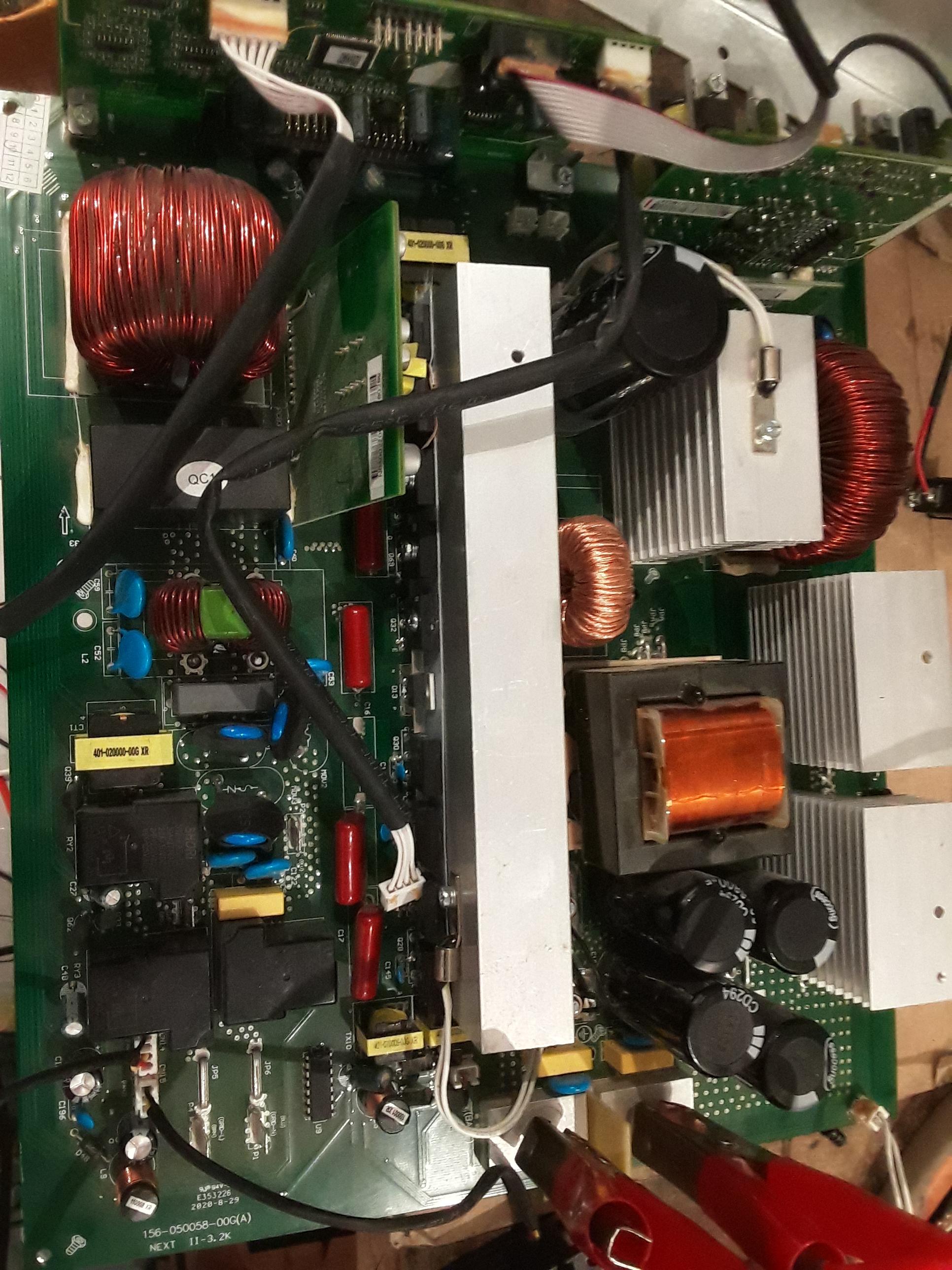
TODAY i got good repair story that will benifit every one i received an inverter 48vdc 5500 watt , the symptoms is burned mosfets and dc-dc igbts i scaned and replaced all bad fets igbts and resistors in both primary and secondery when i turned the device on ,,the inverter on but the seems to be restarting continusly i immediately suspected the main sps when i checked 12 5 and -12 they all ok i checked the battery sps , its output is fluctating like crazy ffrom 120 to 80vdc ...so big ehhha i brought my cigarette and coffee as i know i am in the right path logically what sps is feeding? it feeds the main sps and the soft start so i checked the mppt board as the soft start sps existed there i find a shorted diode.., this certain diode used in mppt as main boost diode and this certain diode i am sure i cheked it when i first opened the inverter it was goood i felt that its replacment wont bring any fruit , but i did replace it any way now as soon as i turned on the device the diode got shorted again and not only it shorted but mppt igbt is shorted as well ....i know i was close ....but i should avoid losing new diode and new igbt i was not sure what to do ....i decided to replace the diode and igbt again but before doing so i replaced all bus 500vdc caps .....when i turned the device on .. the diode and igbt not shorted and the inverter no longer cycles , it gives me error 53..i have seen this error before it is always have some thing to do with the ac igbts ...so i tested the square wave signal in all 4 igbts and find 2 missing pulses i tracked 18vdc -5vdc power supplies and i detcted one diode is too hot there i tested that diode i find it shorted partly ..i turn the device off and replaced the diode ... i powered the device agian and mppt igbt and diode blow again so it seems they survive when i replaced the caps not because i replace the caps but because last igbt was fitted have taken the zener 18vdc diode with it , prevnting 18vdc to reach to the copler that exist in mppt that copler is partly shorted give him 18vdc and he will destroy ur igbts ....a partly shorted copler will miss translate 18vdc into a dc signal that is not on nor off i quck fix i diconnected the shown cable it is responsible for sending the 18vdc to the mppt board i removed bad fet and bad diode from mppt board and fixed new zener 18vdc diode ...truned inverter on ..guess what.....the device worked!! ------------------------------------------------------- failure analysis ...the device have a dc-dc failure and have bad copler the bad coplerand and bad zener loaded the sps cuasing cpu to restart ....although its not logical because main sps seems ok with good zener the 18vdc travel to the mppt board and ruin the igbts there due to bad copler .. with a partly shorted zener 18vdc voltage is not going to travel to mppt board and the igbts will survive but in other hand you wont have your ac as missing 18vdc is used by ac igbts as well with picture you will see the cable that you have to disconnct when repairing i hope you love my story but have 2 questions i did replace bad t350 with good t250 and it worked can i replace bad copler for3150 with t250? will it work ? the "suspected " bad copler have 30k between its 18vdc pin and 5 vdc pin is it normal reading ? the diode in mppt board have the full bus voltage across it 360vdc is that normal?


-
how foolish of me ..yes after diodes and no voltage is going to back fed
-
the units i met all have built in " main smps 12 5 minus 12 " and bettery sps but i guess feeding dc after the " diode or" connections will prevent fed back to battery what so ever i think this can be done to sps configuration where the "oring is done in the battery side and can be also done in sps confirgurations where the oring is done after the battery sps
-
detcting shorts in primary is very fast...uc3842 based smps and other "current mode" control smps's are all super fast when it comes to protection they die due to faulty caps more than they die due to over current incidents
-
I THINK The configuration i am talking about is like shown in my picture i remember i once opened the fuse of the battery sps and the main sps is dead ....its dead not bevcause it is dead but because the battery sps is actually dead and its the battery sps is the one the feeds the main sps ... this is some thing that i personally experinced ....but i assumed that the pv and ac are feeding ored at the output of the battery sps ..i have not actually followed it so am not sure but its more logically to feed the output of battery sps ...........i even met an inverter that have only 2 smps ....one if soft start and other the main i guess that one evey thing is ored to the mains your confiiguration is quite interesting one and very logical all fed into battery bus ored using diode's simplest application ....diode as valve

-
but that will put 48vdc on the battery terminal? the configuration i constanly see is 4 smps one for ac one from battery "battery sps" and it produces voltage that will operate the mains smps 100vdc one is main smps 12 -12 5 one soft start the trick is that battery sps will work from battery produc 100vdc input for that main smps and in that 100 vdc inpu for mains sps is real input for the entire system!!!!!!!!!!!! all other sps are diode ored to it , ac sps and mppt if battery is non existence or so low still ac sps and mppt can directly connect "diode ored to the 100vdc input for the mains sps tha have to work at all costs for the system to turn on ! ----------- ofoucrse there are other ways it can be done but that mainy the most used
-
this is probably why we have alot of catastropchic failures in such inverter , in most smps current mode control have an inhernint over current protection that will shutdown smps soon as short happen ...they rarely fail in a way that blows thier primary side fet due to short in output diodes but with this open loop converter the short in secondery will reflect in primary and blow fets the cpu no matter how fast it still slow to react to this very fast failures i have my bench power supply i remember shorting positive to negative millions of times never fail ..
-
why ? we inject dc to the secondery of the smps ...it is not going to fed back to battery ?
-
a dual shutdown...cpu shutdown sg3525 and to gurantee the shut down they clamp its output dead by switching q60 q61 ..it seems that the catastrophe happen when the q60 61 already on ..and the sg3525 is not off yet ....with sg3525 is still sending pulses ..shoot through short happen between 12 plus to q43 to q60 to minus 12... now the problem is the delay cause by cap and resistor at sg3525xx shutdown pin i mean my question why would any brand of sg35xx would do good with this delay ...if fets on immediately all sg3525xx brands wont benefit form dealy ...theoratically and intuitively speaking!? \
-
i replaced t350 with t250 ....and it worked! go on with your replacement
-
so i think customers will use fridge and air conditioner , so i have to only to use those diodes in the hbridge dc to ac and have to probably heat sink them
-
i have youtube channel that shows how to repair and also he can email me i will help him with sourcing i once bought 220 pces of igbt at 0.5usd 20 were bad ....that is still awosome deal i repaired 10 pces of 3k solar inverter with this super cheap parts my email [email protected] https://www.youtube.com/channel/UCoVLsJIrlpm-Wk_yYKGA9lw my channel link