pongo
Members
-
Joined
-
Last visited
Everything posted by pongo
-
Hello, yes. I installed firmware 269.61 patched by Coulomb: I know there is an official version from Voltronic 69.70 that solve this issue:
-
from https://github.com/syssi/esphome-smg-ii/blob/main/README.md

-
Hello, for SMX II 5.6 kW, RS485. For SMG II, RS232. easun-smx.yaml
-
The S/N matches with inverter sticker. Inverter has internal Wi-Fi datalogger which sends data to some cloud server. DessMonitor is a web portal where to see inverter data. It shares same data with WatchPower Wi-Fi, SmartESS, Energy-Mate, and other apps. I suppose they made some mess on cloud or they remotely upgraded datalogger firmware. I don't know. Main issue I have now is PV production and output data in kWh is no more sent.


-
These are screenshots of 2 deives:


-
Hello, same issue here for my Axpert Max 7.2. Tow instances, same S/N, same DataLogger P/N, but 2 different Dvice Protocol: 2400, 2449. On one instance I can see Total and Daily PV production and Grid Consumption till May 28th, but no other values (). In another instance all values except Production/Consumption starting from May 29th.. Issue is present on WatchPower app, Energy-Mate app, SmartESS app, DessMonitor website.
-
@Coulomb sorry to bother you, is there any chance to have such patch? Thanks
-
Hello, then, if 69.06 is better, could be patched to increase max charge current to 120A (and Max Utility Charge Current as well)? In this way I could have SoC management and 120A charge current (and 90V bug fixed). Thanks PS: when inverter is in SBU mode and is in bypass because battery voltage/soc is lower than "Return to grid" value, MPPT power goes to battery and to load at the same time, and if needed, missing current for load took from grid. Is there a way to let inverter MPPT to charge only battery and let grid to feed only output loads (when in bypass), without mixing solar power and grid power into loads, maybe with a fw patch? I'm asking this because in Italy is not allowed to feed loads from solar and go in parallel with grid at the same time using an off-grid inverter (we need an on-grid inverter certified for italian regulations).
-
Hello, finally I received original firmware from my vendor: 88.03. Differences I can see, comparing with version 69.61: Max Charge current 69.91: 80A 88.03: 120A Back To Grid, Re-Discharge, Cut-Off (parameters 12, 13, 29) when supported battery connected: 69.61: parameters are i SoC % 88.03: parameters are in V Could this firmware be patched for 90V bug, please? Could parameters be changed to use SoC %? Thanks MAX_7.2K_88.03.7z
-
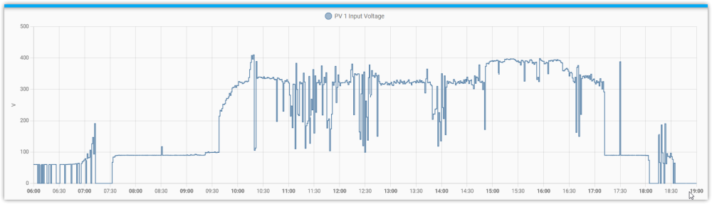
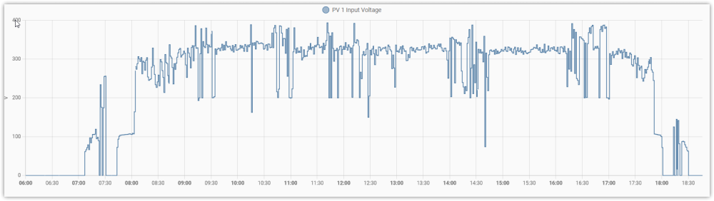
Hello, I installed version 269.61 yesterday. Now I can see Voltage differences on morning and afternoon. Before upgrade (sunny day): After upgrade (cloudy morning): Thanks
-
Thanks @Coulomb I'm waiting for original 88.02 from my supplier. Meanwhile I will try 269.61 (69.61)(Voltronic version numbering is quite confusing). Is safer to upgrade from USB On-the-GO or PC via RS232?
-
Hello, I confirm I have DSP 28066 and this new firmware 69.06 was updated by supplier on my inverter and that now I can select charge current at max 80A, instead of 120A of previous version (88.02). I have the impression 90V bug has not been solved Could this be patched, please?

-
This is fw they installed MAX_7.2K_69.06.7z Could you check, please? They told me that this has 80A charge limit (against 120A of 88.02), has SoC % for parameters 12, 13, 29 when battery type <> USER. Could you check, please?
-
Hello, finally my supplier has updated my inverter firmware from 88.02 to 69.06 (DSP 28066) to solve 90V bug. I will check next days if it truly solves this bug and let you know. I requested also to have original 88.02, so should be patched, but not yet received.

-
Thanks, I confirm now it works
-
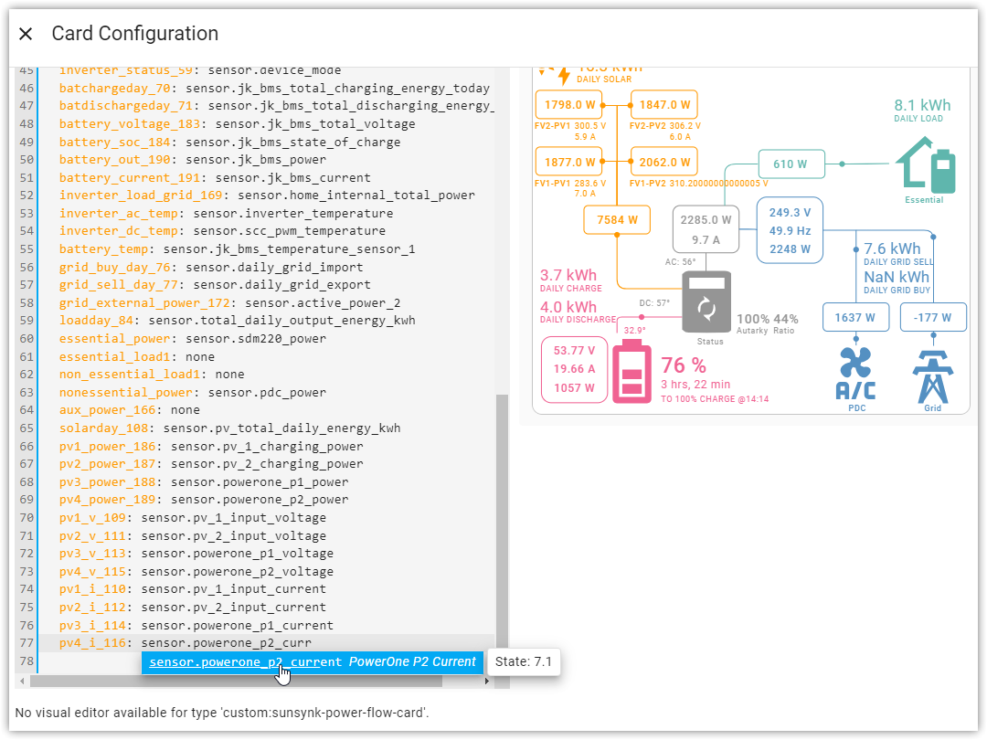
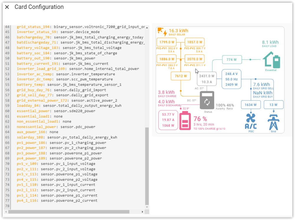
Hello, I tried to configure 4 MPPTs. My 4th current pv4_i_116 doesn't show:

-
Thanks @Coulomb, I will try to contact supplier and see if I could have a firmware file. Thanks
-
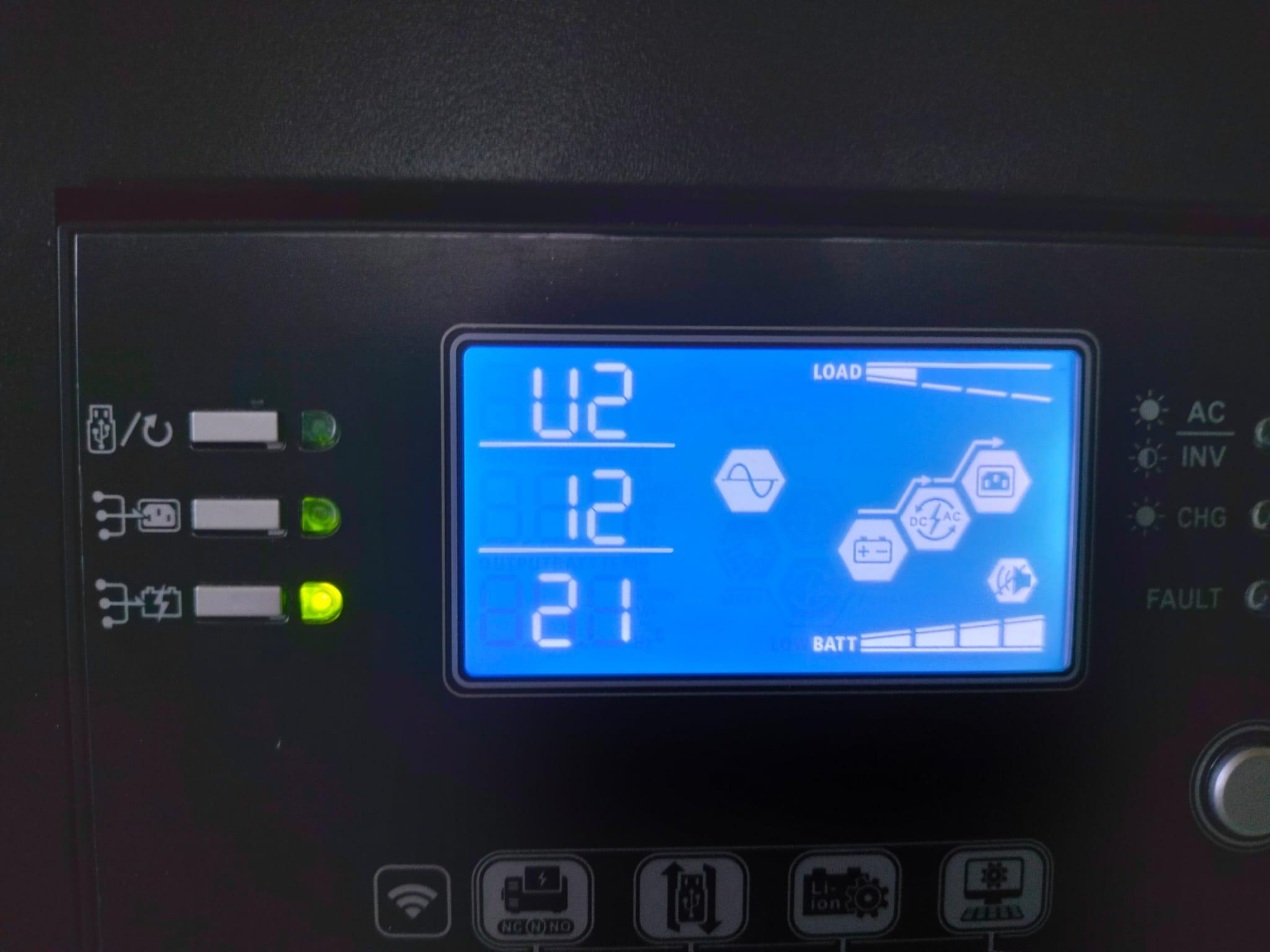
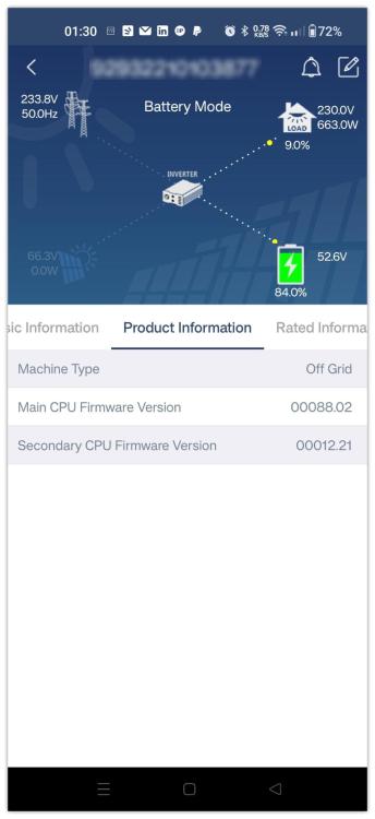
Hello, I have an Axpert Max 7.2k from SolarPower24, with 90V bug at low light. Firmware U1 88.02, Display U2 12.21. I don't know which chip it uses. Which is the best firmware I can install to solve 90V bug? Thanks


-
Would you share your code?
-
Checking on official ModBus specification document MODBUS APPLICATION PROTOCOL SPECIFICATION V1.1b3, on page 15: my conclusion is that LIB protocol is not a standard ModBus protocol implementation, but a custom protocol. For standard modbus protocol, request 01:03:00:33:00:01:74:05 expects response 01:03:02:00:3D:79:95 Looking on another python implementation from @googy (https://powerforum.co.za/topic/10545-bms-communication-with-axpert-max/?do=findComment&comment=112805) response is 01:03:00:01:00:3D:D5:DB Completely different from standard ModBus. So, my assumption that this is modbus was wrong. My conclusions are: I cannot use modbus, I have to implement directly LIB serial protocol on my own.

-
Hello, @Enrico Zanolin I know ModBus protocol... in the past I already developed RTU master clients in C or python. In response, data length should be 1 byte long and should indicate how many bytes contains, as my responses are written. You are right, these are requests from inverter 01:03:00:01:00:02:95:CB 01:03:00:33:00:01:74:05 01:03:00:34:00:02:85:C5 01:03:00:70:00:01:85:D1 01:03:00:71:00:01:D4:11 01:03:00:72:00:01:24:11 01:03:00:73:00:01:75:D1 01:03:00:74:00:01:C4:10 and these are some responses from my ESP32 to those requests 01:03:02:00:32:39:91 01:03:02:00:C0:B8:14 01:03:02:01:E0:B8:5C 01:03:02:01:F4:B8:53 01:03:02:02:44:B9:17 01:03:02:03:E8:B8:FA 01:03:04:00:04:45:C0:89:32 You can see better here [15:12:58][I][ON_READ:187]: address=0x33, value=61 [15:12:58][D][uart_debug:114]: <<< 01:03:00:33:00:01:74:05 [15:12:58][D][uart_debug:114]: >>> 01:03:02:00:3D:79:95 <<< means request from inverter (asking SoC) >>> means response from ESP32 (sendig 61 %). The problem is that inverter didn't accept my responses (they are correct in my opinion) showing error 61. Connection is correct, because ESP32 receives requests from inverter. I don't know if I'm missing some important information that inverter needs or if my responses are not accepted for their format. I don't understand if LIB protocol description is wrongly written or if it really expects response in that format: LEN 2 bytes long, data 2*LEN bytes long (not standard in my opinion). As device I'm using an ESP32 M5Stack Atom RS485 (used also in other projects). Did your code work to communicate with inverter? I would be happy to look at you code, thanks. @Rozsda could you share your solution, please? I never developed CAN protocol. EspHome is my preferred way to proceed, thanks.
-
I implemented dynamic data from BMS to ModBus github/gianfrdp/esphome_yaml/jkbms-voltronic.simple.yaml. EspHome reads relevant BMS data from MQTT and sends over RS485 ModBus RTU. Tested reading values with a python script and it works. Now I'm going to attach it to inverter. I cannot use esphome-jkbms and this implementation on the same ESP32 because esphome-jkbms use framework esp-idf, instead modbus-server component I'm using is only compatible with framework arduino. If I can port modbus-server to esp-idf, maybe I could use just one ESP32, without reading values from MQTT (another possible point of failure). EDIT: I connected ESP32 to inverter, Axpert asks data, ESP32 responses but after some time goes in error 61 (communication lost). Maybe I'm sending something wrong. [15:12:58][I][ON_READ:187]: address=0x33, value=61 [15:12:58][D][uart_debug:114]: <<< 01:03:00:33:00:01:74:05 [15:12:58][D][uart_debug:114]: >>> 01:03:02:00:3D:79:95 This is from LIB protocol documentation: But searching in another project I saw: Response format is different: | Slave Address | Function | Data Len n (1 byte) | n * bytes | CRC (2 bytes) | vs | Slave Address | Function | Data Len n (2 bytes) | 2 * n * bytes | CRC (2 bytes) | Using "Modbus Slave" fot test: DEBUG:pymodbus.transaction:Current transaction state - IDLE DEBUG:pymodbus.transaction:Running transaction 1 DEBUG:pymodbus.transaction:SEND: 0x1 0x3 0x0 0x33 0x0 0x1 0x74 0x5 DEBUG:pymodbus.client.sync:New Transaction state 'SENDING' DEBUG:pymodbus.transaction:Changing transaction state from 'SENDING' to 'WAITING FOR REPLY' DEBUG:pymodbus.transaction:Changing transaction state from 'WAITING FOR REPLY' to 'PROCESSING REPLY' DEBUG:pymodbus.transaction:RECV: 0x1 0x3 0x2 0x0 0x3d 0x79 0x95 DEBUG:pymodbus.framer.rtu_framer:Getting Frame - 0x3 0x2 0x0 0x3d seems response format ESP32 is sending is correct... so I don't understand why Voltronic reports error 61 jkbms-voltronic.simple.yaml


-
It needs to connect battery to see inverter asking modbus values. Now it works. These are registers my Axpert Max 7200 is asking: 01:03:00:01:00:02:95:CB 01:03:00:33:00:01:74:05 01:03:00:34:00:02:85:C5 01:03:00:70:00:01:85:D1 01:03:00:71:00:01:D4:11 01:03:00:72:00:01:24:11 01:03:00:73:00:01:75:D1 01:03:00:74:00:01:C4:10 01:03:02:00:32:39:91 01:03:02:00:C0:B8:14 01:03:02:01:E0:B8:5C 01:03:02:01:F4:B8:53 01:03:02:02:44:B9:17 01:03:02:03:E8:B8:FA 01:03:04:00:04:45:C0:89:32 Continuing testing and trying to send BMS values Thanks
-
Hello, @BritishRacingGreen, @Rozsda, @PetrDubi could you share your implementations? I'm also trying to implement something to connect JKBMS to Axpert, I tried with LIB. It works perfectly if I use pymodbus to ask values, but inverter doesn't ask for ModBus on BMS RS485 port (setting battery type to LIB). Attached my EspHome yaml file (values are for test only, if it works I will try to take data from BMS). The relevant part is under "modbus_server". Thanks modbus_server: - id: modbuserver uart_id: intmodbus address: 1 # slave address holding_registers: - start_address: 0x30 # 0x0030 | 2 | Module charge current | 0.1A | Summary data of all packs Sum of charge current, is 0 when discharging default: 100 # 10 A default value number: 1 on_read: | ESP_LOGI("ON_READ", "This is a lambda. address=0x%x, value=%d", address, value); return value; - start_address: 0x31 # 0x0031 | 2 | Module discharge current | 0.1A | Summary data of all packs Sum of discharge current, is 0 when charging default: 0 # 0 A default value number: 1 on_read: | ESP_LOGI("ON_READ", "This is a lambda. address=0x%x, value=%d", address, value); return value; - start_address: 0x32 # 0x0032 | 2 | Module voltage | 0.1V | Summary data of all packs Average voltage of all packs default: 48 # 48 V default value number: 1 on_read: | ESP_LOGI("ON_READ", "This is a lambda. address=0x%x, value=%d", address, value); return value; - start_address: 0x33 # 0x0033 | 2 | SOC | % default: 50 # 50% default value number: 1 # number of registers in the range on_read: | # called whenever a register in the range is read // 'address' contains the requested register address // 'value' contains the stored register value ESP_LOGI("ON_READ", "This is a lambda. address=0x%x, value=%d", address, value); return value; // you can return the stored value or something else. TODO: take values from BMS - start_address: 0x35 # 0x0034 | 4 | Module total capacity | mAH default: 0x45C0 # 280 Ah default value | 280000 = 0x4 0x45C0 = 4 17856 number: 1 on_read: | ESP_LOGI("ON_READ", "This is a lambda. address=0x%x, value=%d", address, value); return value; - start_address: 0x34 # 0x0034 | 4 | Module total capacity | mAH default: 0x4 # 280 Ah default value number: 1 on_read: | ESP_LOGI("ON_READ", "This is a lambda. address=0x%x, value=%d", address, value); return value; - start_address: 0x36 # 0x0036 | 2 | Pack parallel number | Number of online packs default: 16 # 16 default value number: 1 on_read: | ESP_LOGI("ON_READ", "This is a lambda. address=0x%x, value=%d", address, value); return value; - start_address: 0x70 # 0x0070 | 2 | Charge voltage limit | 0.1V default: 580 # 58.0V number: 1 on_read: | # ESP_LOGI("ON_READ", "This is a lambda. address=0x%x, value=%d", address, value); return value; - start_address: 0x71 # 0x0071 | 2 | Discharge voltage limit | 0.1V default: 480 # 48.0V number: 1 on_read: | ESP_LOGI("ON_READ", "This is a lambda. address=0x%x, value=%d", address, value); return value; - start_address: 0x72 # 0x0072 | 2 | Charge current limit | 0.1A default: 500 # 50.0A number: 1 on_read: | ESP_LOGI("ON_READ", "This is a lambda. address=0x%x, value=%d", address, value); return value; - start_address: 0x73 # 0x0073 | 2 | Discharge current limit | 0.1A default: 1000 # 100.0A number: 1 on_read: | ESP_LOGI("ON_READ", "This is a lambda. address=%x, value=%d", address, value); return value; - start_address: 0x74 # 0x0074 | 2 | Charge, discharge status # Bit: 7 | 1 | Charge enable | 1: yes 0: request stop charge # Bit: 6 | 1 | Discharge enable | 1: yes 0: request stop discharge # Bit: 5 | 1 | Charge immediately | 1: yes 0: no (SOC <= 9%) # Bit: 4 | 1 | Charge immediately2 | 1: yes 0: no (9<SOC<=14%) # Bit: 3 | 1 | Full charge request | 1: yes 0: no # Bit: 2 | 1 | Small current charge request | small current charge request, allways 0 # Bit: 1 | 1 | | # Bit: 0 | 1 | | default: 192 # 0xC0 1100 0000 number: 1 # number of registers in the range on_read: | # called whenever a register in the range is read ESP_LOGI("ON_READ", "This is a lambda. address=0x%x, value=%d", address, value); return value; // you can return the stored value or something else. jkbms-voltronic.yaml
-
You don't need HomeAssistant, you need to install EspHome. And you need original yaml file where you can change everything (including wifi password). Inside yaml file you can enable/disable HomeAssistant integration and also can send data to domoticz: If you put api: you enable HA integration, if you don't then no integration. To send data to domoticz: sensor: - platform: modbus_controller modbus_controller_id: dds666 name: "Active Power" id: ${id_name}_active_power register_type: holding address: 0x2004 unit_of_measurement: "W" device_class: power value_type: FP32 accuracy_decimals: 1 filters: - multiply: 1000 on_value: then: - mqtt.publish: topic: domoticz/in payload: !lambda |- std::string messageO; char str[256]; snprintf(str, sizeof(str), "{\"idx\":25666,\"nvalue\":0,\"svalue\":\"%.2f\"}", x); messageO += str; return messageO;