RudShep
-
Posts
17 -
Joined
-
Last visited
RudShep's Achievements
")


-
 Riyad179 reacted to a post in a topic:
Growatt SPF 5000 ES Error 02 - Solved
Riyad179 reacted to a post in a topic:
Growatt SPF 5000 ES Error 02 - Solved
-
Hi all, You know what to do when you switch on the battery and hear a poof and smell smoke right? Just switch off and press the Undo button. Yeah right, I wish. I connected a Giter "48V" lithium battery to a Full Circle Solar 5kw. It's been working for months on lead acid. I switched on using the DC breaker and then heard a clicking/sparking sound (not relay) and the inverter display is blank and switches on and off rapidly in a loop. After the initial WTF moment I started looking at numbers and saw this... Measured Battery Voltage 53.5V DC input 48V DC charger output 54V The battery is nominal 48V and operates to 57.6V. I think it must be a 16 cell and not the usual 15 cell. Is it possible that the voltage is too high for the inverter or was it inrush current or something else that killed it? All I can see are some low voltage caps 16V being bulged around the 7912 (-12V) regulator. Could the damage be limited to this or should I look further? Am I wasting time trying to repair it? Any advice will be highly appreciated.

-
Coulomb reacted to a post in a topic:
Growatt SPF 5000 ES Error 02 - Solved
-
ErichK reacted to a post in a topic:
2 Inverters, 1 battery bank, not parallel
-
I ended up installing a second DB above my original DB because of the space constraints. So mains up to the change-over switch and back to essential circuits. I left the essential breakers in the bottom DB but moved them to leave a space for a blanking plate in between to physically see the split. What I found helps more than anything else is to have led indicators on each of the inputs and outputs. If any lights are on don't touch anything. Saved my bacon more than once.
-
Is it this one? I'm desperately looking for a 3kw manual. The one in the box is for a completely different inverter and the settings are cryptic as h3ll.
-
And check that your installer has an account with the supplier and will honour the warrantee. I got burnt by a purchase from a guy who bought from a reputable supplier, but couldn't provide the original invoice when it broke so the supplier said sorry Sam. Need the paperwork. Register your equipment for the warrantee as soon as possible after installation.
-
I would speculate the original setup was sized for 2x batts @ 20A charge current each = 40A plus change on the DC breaker. Since adding the 3rd battery, the BMS is telling the charger it is okay to send more amps now or 100A in your example, but the breaker can't take it and trips when the sun shines bright. I guess you could put in a bigger breaker or fuses but judging from the wiring I wouldn't risk such high current. Rather set the inverter to limit the charge current to what the cables are rated for - or replace your DB and cabling. Charging will take longer but it is safer.
-
I wouldn't think drawing from a battery bank in parallel should be a problem, but hitting it with two chargers in parallel might cause an issue if they don't know about each other and try to get "smart" with the charge curve. If you can get away with it, charge with one charger and disable the other or use one charger for PV and the other for utility charging. It might also be more efficient to put a DC element in the geyser and drive it directly from the panels but it is still not nearly as efficient as a direct solar water heater if that is an option. You get 1kw equivalent per square meter on a water heater, but a 1kw PV is probably 2 or 3 sqm or more roof space. In my own setup I use the geyser (with a standard element) as an "excess energy battery". I monitor the PV supply and the load and if there is more supply than load, the excess is pumped into the geyser. This goes on the whole day, little by little, until it is hot. It is called an energy diverter... look at emonCMS energy diverter for ideas. The algorithm also switches the geyser off if there is other demand to not overload the inverter. It's a bit finicky at times but interesting.
-
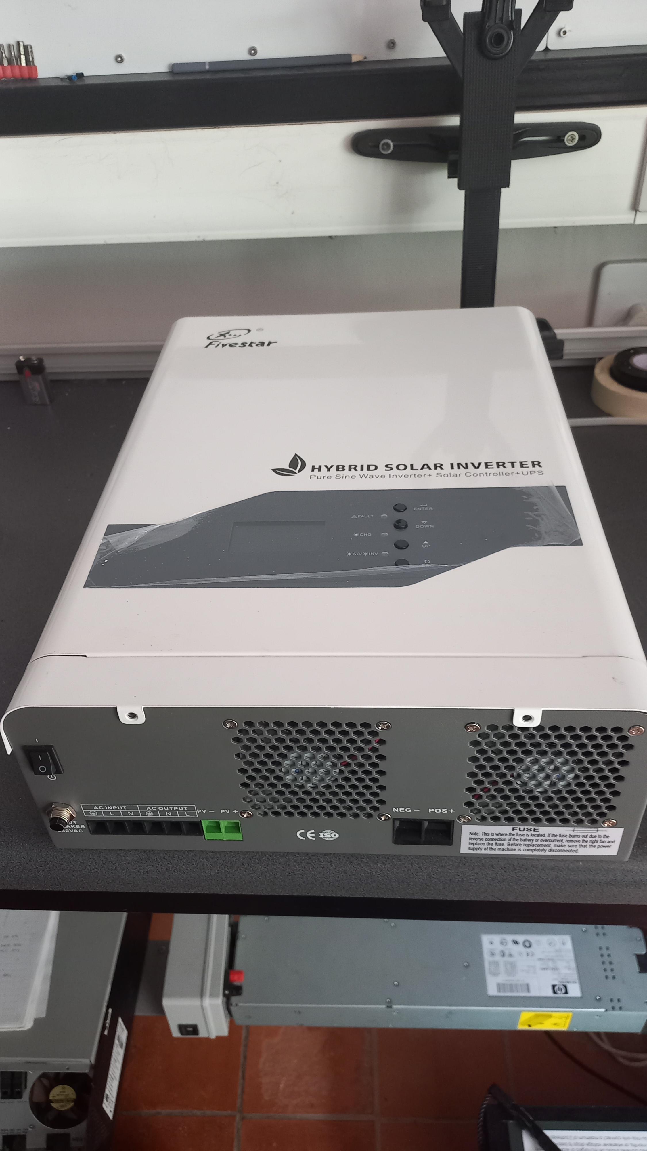
Hi all, I have this Fivestar branded inverter on the bench but is not like other clone inverters I've seen before. The manual in the box is Voltronic/Axpert'ish but the settings on the machine is completely different. I'm looking to identify the OEM brand so I can get the proper manual and figure out what Fault 134 is. Anybody have an idea?
-
BritishRacingGreen reacted to a post in a topic:
Growatt SPF 5000 ES Error 02 - Solved
-
zsde reacted to a post in a topic:
Growatt SPF 5000 ES Error 02 - Solved
-
ConradNK reacted to a post in a topic:
Newbie Needing Some Help Growatt - 5KW 48V Hybrid Inverter + N ENERGY 48V
-
Hi all, I had quite an interesting but satisfying journey hunting down the cause of Error 02 on a Growatt inverter and share the story to spare you future pain. It started with the inverter starting up with warning 02 (overheat) despite ambient showing 25 on the display. I noticed that when it rains, or there is high humidity, the warning turned into an Error and the inverter would just cut out for safety reasons. It would then magically repair itself after a while and work again. Until the other night the Error 02 kicked in with vengeance and no more Netflix during load shedding for me. This is a second hand unit I picked up from someone that lives close to the sea and clearly got fed up with it. The proximity to the ocean is a big clue. I noticed right off the bat the build-up around the fans and white spots on the PCB inside. I'm presuming these are salt deposits, but could also be some other acid carried on the ocean breeze. This is AFTER cleaning! To cut a long story short, the cause of the Error 02 was the thermistor connector on the MPPT board was eaten away and the pin crumbled into rusty dust when I touched it. Here's a pic of the offending part... And after a quick repair... I was ecstatic to find the fault and quickly replaced the connector, put everything back together and fired the inverter back up. Wha, wha, whaaaaa.... *FAIL* Ag no man... what now? After stripping the whole thing again, cleaning every piece of build-up off the boards with a toothbrush and alcohol, I noticed that in some places the track would just crumble and fall off the board! I should have noticed it in the pic above already, but was blinded by the first and obvious fault, like so often happens. I noticed the big trace from the one connector to the other side of the board but when I tested it, it was not conducting. A little more cleaning revealed a the trace has disintegrated. The fix was quick and easy... although the same cannot be said about finding the problem in the first place... I was so annoyed I forgot to take a picture of the fix, but all it is, is a jumper wire across the broken trace. So all back together it goes and soak test on the bench. I call that a win! So back to the root cause... The fans seem to pump an awful lot of caustic moisture over a sensitive part of the board. There is a plastic coating sprayed over the components but on this inverter, it wasn't done very well and the rust got in everywhere the barrier was weak. Growatt really needs to have a look at this. So the moral of the story is, if you are going to install a budget inverter at your huisie by die see, put it where the salty breeze can't get to it, put a filter over the fans, or put in a waterproof inverter. I hope this helps someone. Epilogue... The story didn't end here.. Fixing this fault exposed yet another... have a look at the post about the 350V AC problem for more fault finding fables.
-
I think you have a problem might be with the cable pin-out. It should be pins 1, 2, 3 on the battery side to pins 1, 2, 3 on the inverter side. Straight through in other words. The battery only supports RS485 and not CAN. Rudie
-
Solved! Here's the cause if someone else runs into it. There is a string of 4+4 330K sense resistors that feed the AC voltage to the processor. These guys are really close to the intake fan and something seemed to have corroded away the pad on the PCB. Probably the salty air here at the coast. Makes sense because another corroded track was the cause of the Error 02 as well. Because the track was not completely broken, it sometimes worked and sometimes not. With temperature or humidity fluctuation, it would magically start working or stop working, you never can tell. I repaired it by re-soldering the resistors and repairing the track. All good and stable for 24 hours on the bench now. PS. This is a typical "replace the motherboard" problem, solved for a couple of Rands and a bit of time. Fair and well if under warranty but expensive if not. Not to mention the perfectly good electronics going into landfill and killing the sea turtles. I really think all of us have the responsibility to try and repair something before we rip and replace it. It's not only good for the pocket but also for the environment. PPS. Growatt needs to attend to this. It is not the first inverter I found with salt damage and it is dangerous. I saw it kick in at 260V and supply the load with the high voltage - enough to fry something (in a non-foodie way). There is a protective coating over some areas of the board, but quality control failed you here because the coating was very spotty in this area. Put more moisture protection in the area by the fans please. People in my area are throwing out Growatts and putting in SunSynks by the truckloads because the SunSynks are IP65 and weatherproof and the Growatts lose their marbles when it rains for stupid reasons like this.
-
chelin reacted to a post in a topic:
Newbie Needing Some Help Growatt - 5KW 48V Hybrid Inverter + N ENERGY 48V
-
ConradNK reacted to a post in a topic:
Newbie Needing Some Help Growatt - 5KW 48V Hybrid Inverter + N ENERGY 48V
-
Antonio de Sa reacted to a post in a topic:
Newbie Needing Some Help Growatt - 5KW 48V Hybrid Inverter + N ENERGY 48V
-
Hi Conrad. DON'T use AGM... the voltages are wrong for Lithium. As zsde said, use USE mode and set the parameters to what the battery manual says. Post a page or the entire manual here and I can try and help. You can run on USEr defined mode but it is certainly better to get the inverter and battery to communicate with each other via the comms cable. Trouble is there are over 15 "profiles" on the Growatt and two ports - CAN and RS485 so it is hard to find a combination that works. I am busy setting up a bit of a database of inverter and battery combinations and settings and will be happy to go through the pain to get yours working with you to get some data for the register. Rudie
-
Hi all, I recently repaired a Growatt 5000 ES with a Warning 02 (overheat) that turned into an Error 02 that shut it down. I'll post the cause and fix in another thread but suffice to say it was a connector and track to the thermistor on the MPPT board that was corroded by the salty Garden Route air to the point of giving false readings and eventually created an open circuit in the track leading to 02 error. When I put the inverter back in service I noticed it started up showing a ridiculous Eskom AC input voltage in the 350-380 range. It did so before but settled down quickly. This time it also started jumping all over the place and eventually came down to threshold level and jumped between 180 and 250 and the inverter kicked the relay in and out repeatedly. It was a bit scary as it clearly was very confused what to do and just kept cutting in and out. No load at this point. I shut it down and put it back on the bench. By the way it works perfectly from battery only. I then fed it from the output of another inverter at exactly 230V measured with the multimeter at the terminals. It showed 350V and slowly came down until it settled at 240V a few minutes later. Then I switched to Eskom again and still showed 240 with actual input of 225V. I left it switched off for 4 hours or so and now it started up AC only at around 280V on an actual of 232V. When I switch the inverter on, it does the clicking in and out again and there is a disconcerting sparking sound coming from inside. Starting up on battery works fine and bringing in AC shows 410V (yes!) dropping to 270V and staying there. Any ideas? Could it be the AC measurement circuit that has a faulty component and any suggestion where on the board to look for it? By the way I fixed another Growatt with weird behaviour by just cleaning the board from the salt build-up. Looks like when the salt gets wet from high humidity it conducts and throws the sensors off. Not in the latest case though... already sparkling clean. Rudie
-
Had the same. I used to have an 3kw Axpert on light circuits only but when the 5kw Growatt was installed in its place, earth leakage tripped all the time. It cost me having to split the neutrals on the DB board so the circuits running on Eskom do not share a neutral with circuits running off inverter. Refer to the SANS diagram to do it right. It is expensive with the extra components needed, not to mention time, but important for safety. Incidentally we found an un-earthed plug during testing afterwards. A proper hazard left by the previous house owner. The temptation to install an inverter like a generator into the house wiring is big but not worth it. Rather make yourself an off-grid "power trolley" that plugs into the wall to charge and appliances plug into an extension cord from the trolley - until you can get a qualified person to rewire your DB and install permanently. Don't forget to put an earth leakage detector on the DIY power trolley too.
-
Hi all, Do you perhaps know if there us a repair capability for Axpert, Mecer, Growatt, Kodak, Goodwe inverters in the Garden Route area? George, Mosselbay, Knysna, Plett. There seems to be a lot of repairable devices that can go back into the economy but not finding skills in the area to take on the opportunity. Rudie