


Pieta
Members
-
Joined
-
Last visited
Everything posted by Pieta
-
It seems that the 90.19 upgrade does help. Have seen an interesting review of the problem and what seems to be causing it. Unfortunately with Spanish comments but translated you can get a better understanding of the causes of the problem that it seems that it has now been sorted with the upgraded firmware . Also with some interesting photos of the 7.2 max inside! Also that the 7.2 might soon be replaced with the 8Kw version? https://www.solarweb.net/forosolar/fotovoltaica-sistemas-aislados-la-red/48226-voltronic-axpert-max-review-profundidad-2.html
-
Bruce hope you got right? That is the correct port. If not try to set the port to Com1 in the Device manager as the other port numbers sometimes do not work with peripheral USB to serial converters
-
Hi Coulomb Thanks for the info! That now make more sense on this type of inverters. Have also picked up that if two 7.2's are used in parallel then the battery current is still limited to only 80 Amps. This means it is then limited to 40 amps only per inverter? Full current is however available for the load... Not sure if this is normal? Maybe you can help? Regards Piet
-
Hi Bruce Try to make your com port - COM1. Specially if you use USB to serial converters when you do not have a dedicated serial port on PC. This sometimes helps...
-
Thanks Plonkster for the reply! I believe that most of the standby ups systems with bypasses today then also do not comply as the bypasses of these systems works very similar to this layout. The 4mm air gap might be a valid point...
-
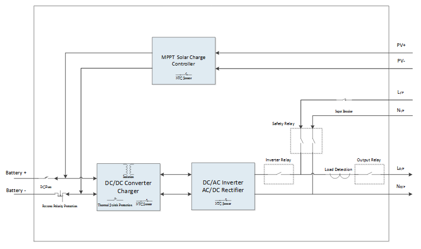
Hi, Wikipedia "A grid-tied electrical system, also called tied to grid or grid tie system, is a semi-autonomous electrical generation or grid energy storage system which links to the mains to feed excess capacity back to the local mains electrical grid." Why is the Axpert seen as a grid tied inverter? The way i understand it is that the Axpert is an off grid inverter. (Might be wrong - Please help me to understand this if i am wrong?) At no time is the inverter output connected directly with the Grid. (Except maybe in a severe fault condition and the safety relay did not operate and stands in the closed position? This can also happen with any other machine in fault condition) There is a double pole input safety Relay feeding the Grid supply There is a load output relay connecting the load either to the Grid when the Safety Relay closes and inverter is switched off or to the inverter output when inverter is switched on and Safety relay is open. There is an inverter output /charging input relay connecting the Inverter output to the load in the first case (Safety relay opened in this case) or to use the Grid to charge the batteries (Safety relay closed in this case) The controller either connects the Grid directly to the output load and at the same time giving Grid supply for charging the batteries. Or in the next case the controller disconnects from the grid with the Safety relay and then only connecting the inverter feeding directly to the output load . At no time are these two directly connected (Inverter when feeding output and Grid supply). That is why there is a transfer time of 10ms to 20ms. Similar to a off line UPS system. On a grid tied system there are usually no period when the output switches off momentarily (Dark chop-over) as transfer from grid to inverter or inverter to grid takes place with connection of both inverter and Grid together for the period of time while transferring load. (Life chop-over due to synchronization that makes it safe) We can see that the Grid might feed into the rectifier/charger to charge the batteries or that that the solar can charge the batteries with DC to DC Buck/Boost converter but this is controlled to put out a DC current to charge the battery or to feed the DC bus. However at no time can the controller switch on the inverter when the Grid safety relay is closed. In a Grid tied system the input and output of a grid tied inverter needs to be syncronised with the Eskom grid to enable any feedback into the Eskom grid. If synchronization has not been achieved and the output connects with the Grid an out of phase condition will occur that will probably cause severe damage. As far as I understand the Axpert never syncronise with the grid for the intention to feed back to the grid. (Reason for Dark Chop over) Would like some feedback to understand better? Regards Pieta
-
Gabriel sure if you can sort out the comms problem you would be able to reflash it yourself without getting it bricked by an "a"xpert! Always nice to learn by doing it yourself and there is really very good reading material on this forum to help. After all the prep work for the big rains you might still have some time to sort it before the warranty expire!
-
These serial to Usb Devices usually select higher Port numbers when installing and if installed to a higher port number it might not be seen when you select Port 1?
-
Hi Gabriel Check in device manager if Communication Port is selected to Port 1?
-
Thanks for the Info! Agree with you there are definitely a difference from the indication to the real values! Will have some time the weekend to play around again. At least we are on the right track... Thanks a million!
-
Hi , First off all thanks for all the amazing topics that are available! For a newbie like me on Solar this certainly helps a lot!!! Wonder if someone can help? It might have been discussed before but I could not find anything on the problem as set out below... Have written a program in VB6 (Please don't laugh!!!) to interface with 2 x Axpert 5KVA Inverters but has found a problem as the PV input currents does not add up...When measuring current from the Solar panels to the inputs of the Axpert Inverters with an amp probe the current seems to be less than the current indicated as PV Input current on the Inverter display and different software available. The PV input voltages however are more or less the same when measured with a multi-meter. If the Wattage of the Solar panels are calculated by multiplying PV Input currents measured with an amp probe and with the PV input voltage measured with a multi-meter then there seems to be an error. It seems that the PV Input Current shown on the inverter is actually not the PV Input current but the MPPT output current. We think that the PV input current readings that we get from the inverter display and when polling is measured only after the MPPT's has already made its conversion. That is why the PV input current that is displayed is higher as when measured with an amp probe on the Solar input side. All the information are not available when polling with QPGS and a ratio has to be used to get to the correct Solar PV input current. We think this can lead to incorrect Solar panel input wattage display. We have used the ratio of the Battery voltage divided by the PV Input voltage and then multiplied by the "PV Input current" (MPPT current) as given when polling to give the real PV Input current. PV input volts x PV input current = MPPT output volts ( Same as battery voltage ) x MPPT output current (Battery and Load current when in inverting mode - This is similar to the ratio of transformer input to output voltages and currents) When we use this ratio the PV Input current before the MPPT's are more or less the same as when measured with the amp probe. There might be a slight difference due to losses. Hope someone can maybe lead us in the right direction if we misunderstand the concept. Kind regards Pieta
-
Hi Daniel We see it that when current flows in any circuit that has resistance then volt drop will be experienced over that resistor. (That is the reason why you can use a shunt resistor to determine current flow (V = I.R)) If a shunt resistor is used to determine current flow in a DC circuit you keep the resistance of the Shunt as low as possible to have very low volt drop over the resistor when current is flowing through it. Usually in milliVolts output to keep the Wattage or heating component as low as possible. The wattage is determined by the Volt drop over the Shunt multiplied by the current flowing through it (P=V x I) The Volt drop over the resistor is directly proportional to the current that is flowing through it. (A 600 Amp 50 mV shunt will give out 25mv when 300 Amps flows through it) The same thing will happen when batteries are charged in series. There will be volt drop over each cell/Battery. Volt drop over each cell or Battery is determined by the current flowing through the string in series and the resistance of each cell. If the resistance of the batteries are different then different volt drops over each of the cells/Batteries will be experienced. This out of step condition causes some of the cells/Batteries to overcharge and some to undercharge. Differences between cell/Battery voltages indicates this condition. Obviously all cells/Batteries will not have exactly the same resistances but it should be kept as near as possible to each other. This is where the use of battery balancers come in. Overcharging will definitely cause overheating of these cells/Batteries with the higher resistances and voltages cells/Battery as the Wattage component (P=V x I) becomes more on these cells. Unfortunately if the cells/Batteries are kept in this state for too long damage might occur.

