Abra
Members
-
Joined
-
Last visited
-
Aaaaaand one moment. Problem with Charging from PV and AC still there But I think it will be more easier Now it chaged to: input AC to output AC working well input AC to batteries not working input solar to output AC working well input solar to batteries not working batteries to output AC working well So, need to check again this?
-
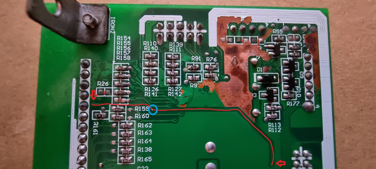
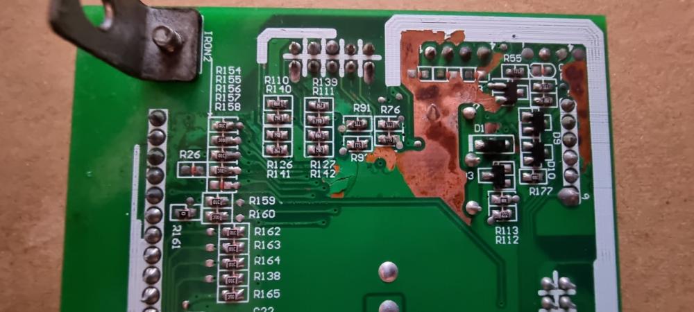
Thanks to everyone for pointing me in the right direction, it remains to check all the boards in these areas and repair the damage. The topic started as error 52 but then grew into something more. All in all. The post concerns 5kW Axpert, MKS II, etc. and Warning 15!, problems with the screen, control buttons (On one control board, the screen began to fail, the button connector is also nearby), the problem of current flow from the PV to charge or output. In the design of my inverter, I think not only mine, the upper left air duct, or rather its lower part, is directed to the upper part of the control board. Where are a lot of important components and connectors located: When working outdoors or in a dusty room, and this is especially unpleasant in combination with increased humidity, a very thick layer of dust accumulates over time on the top of the control board. I have accumulated a layer of about one millimeter, unfortunately I did not take a photo. Also, due to high humidity, especially in the morning, this dust eventually corrodes the protective layer of the board and the tracks that go very close to each other are exposed. Subsequently, if I understand correctly, this can lead to short circuits and burnouts or the decay of some parts of the tracks. In my case, after cleaning the board from swollen paint, the board looked like this: The main problem was this track, on 2 boards it was damaged in the place marked with a blue circle, on another it was damaged in several places, including in the place marked with a blue circle: I also think it is necessary to check all the tracks for integrity before the end of the repair. As for preventing such destruction, I will block off part of the duct so that dust does not accumulate in this place, but flies higher. p.s. My problem and repair for one of the boards looked something like this. It's not that hard, even for a clumsy newbie like me:




-
-
-
The result of my crooked hand soldering. At first I tried to join with tin, but then I realized that I had crooked hands and joined with two twisted strands of wire. I'll clean up the soldering dirt later when I check the rest of the tracks and then paint over with a protective layer when it comes to me. In the near future I will finish everything, check if everything works well and try to give a detailed description of the breakdown, how to check and where to fix it. Perhaps someone will come in handy.

-
YEEEEEEEEEEEEEEESSSSSSSSSS! THIS IS IT! On two boards for sure! The track was damaged in approximately the same place! The second inverter is now working! Tomorrow I will check the tracks on all the boards and connect them with a wire! I checked with a tester. Firstly, charging does not stop when checking, and secondly, it now shows 18.9v.
-
So, I made a mistake, and checked the wrong contact on the Control Board. I found the right contact and found the break in the track! Now I'll try to fix it. I pried the paint off with a feeler gauge and under it like this.

-
Before resistance, the tracks lead here: All tracks and resistance on the control board are fine...

-
Measurements show ~100 ohms from pin 6 on the control board, to the 2nd pin of R183, i.e. track + resistance on the control board show a total of ~ 100 ohms.

-
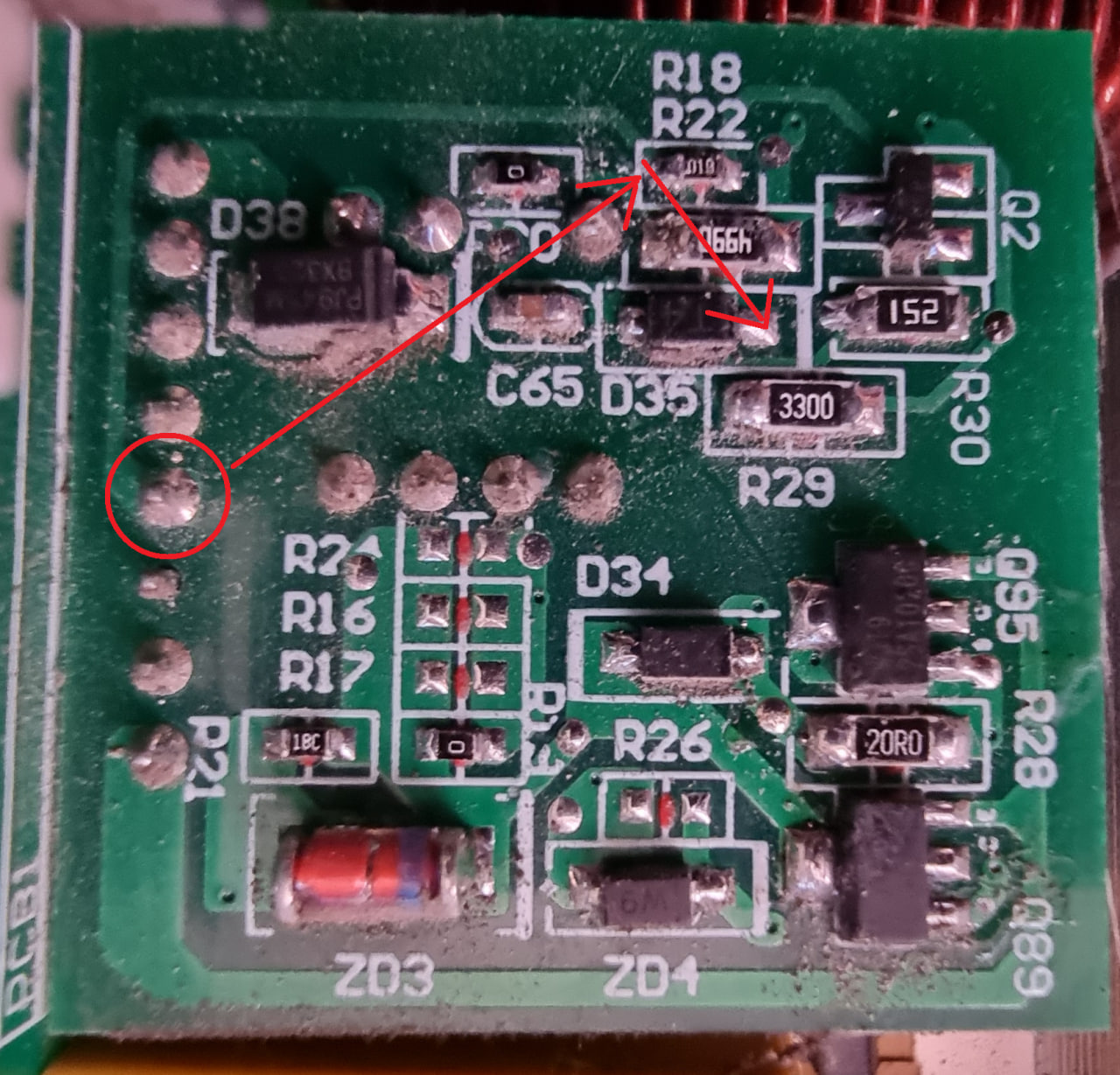
On the SCC board, this pin leads to the transistor driver board. First like this: And then on the transistor driver board right here: (This is an SCC board from a freshly opened inverter, I haven't had time to clean it from dust yet )

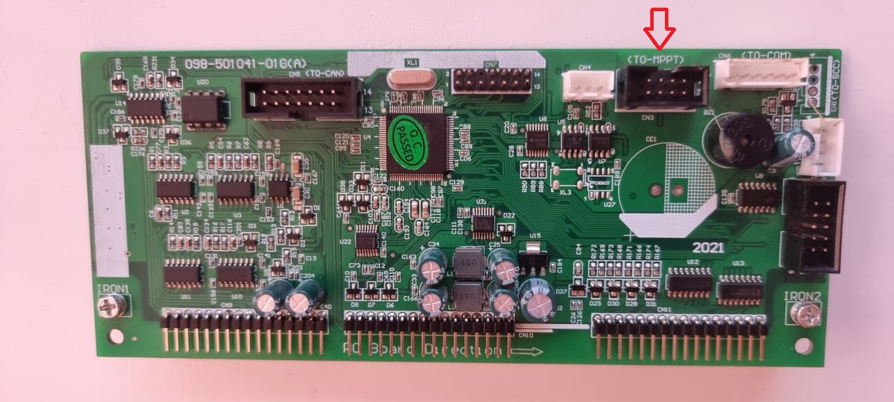
 On the control board, this pin goes to this resistor:
 UPD: 1 column: Control board original from Working one 2 column: Control board original from semi working one 3 column: Control board from 3rd broken invertor 4 column: Control board from 4th broken invertor So what's the point of all this. I went up to the inverters now, to see what works, what doesn't. And I see this. Both inverters are charging, although the control board from the non-working inverter is installed on the half-working inverter. Payment from column 4. I'm starting to measure the pins. And what is happening. When measuring pin 6, charging immediately stops, the pin shows 23.8v. After 2-3 minutes, charging continues again as if nothing had happened. I'm trying to measure this pin again. Charging stops again, then resumes again, and so on ad infinitum. On the worker, when measuring, charging does not stop. Here is an interesting behavior associated with pin 6 I noticed. Not only does it show different voltages with a working inverter, but also when trying to measure, if charging suddenly starts, charging stops immediately. I understand the somewhere problem is here.UPD: 1 column: Working one (Shows around 2.5kW on input PV when measure) 2 columb: Broken one (Shows 0 watt on input PV when measure) 3 columb: Broken one (Shows 40-50 watt on input PV when measure) 4 columb: Broken one (Shows 0 watt on input PV when measure) 1 - ground. 2 - 12.5 => 12.4 => 12.4 => 12.6 3 - 13.0 => 13.2 => 13.2 => 13.3 4 - 17.0 => 16.9 => 16.9 => 17.0 5 - 12.4 => 12.0 => 12.0 => 12.0 6 - 18.5 => 23.9 => 23.9 => 23.8 !!! this pin have a big difference between working one and all brokens. 7 - 23.9 => 23.9 => 23.9 => 23.9 8 - 12.0 => 12.0 => 12.0 => 12.0I ordered this one, I hope I did everything right https://www.lazada.co.th/products/relife-rl-uvh900-rl-uvh900b-rl-uvh900bl-curing-solder-mask-ink-10cc-i1979182474-s6335332797.htmlAnd you can throw off an example of coverage, I'll try to find something similar here. I have not come across this yet Therefore, I don’t know what exactly is needed for coverage Do you think PV may not be charging due to the fact that there is simply no coverage?Yes, the coating was bubbling. I removed most of the paint with just a toothbrush without acetone. Then I additionally rubbed with acetone stronger to wipe off the dirt and remnants of peeling paint.