jbroo
-
Posts
108 -
Joined
-
Last visited
jbroo's Achievements
")


-
I did look for these but found no string. My model looks very much like @Adri76's one inside. I did not check the back of the PCB. Perhaps they are rear mounted.
-
@Adri76 it seems I have the same issue as you. Voltage too high, voltage too low, but never right. Fluctuations of 1-2v. Mostly it over-reads and it thinks the batteries are full but they're sitting at 26v (and it shows 28+). Tonight I opened up the inverter and cleaned and sprayed contact cleaner everywhere. No dice. Have reset all settings to default, still the same. No amount of calibration attempts seem to work. Sad. I got the machine last year.
-
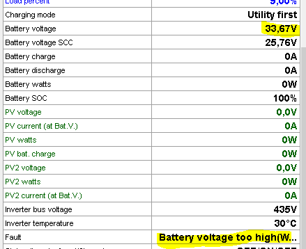
Update: It was somewhat accurate in the beginning, but it keeps drifting further with each day... Note the battery overvoltage fault. SCC voltage remains accurate.

-
SolPipLog and MultiSIBControl can do this. Both are free.
-
Thanks! It could indeed just be cold solder joints in need of a re-flow.
-
 jbroo reacted to a post in a topic:
Synapse (Voltronic/Axpert) battery voltage calibration - help?
jbroo reacted to a post in a topic:
Synapse (Voltronic/Axpert) battery voltage calibration - help?
-
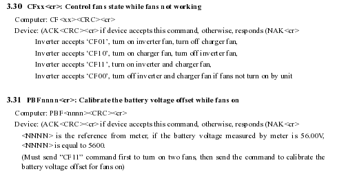
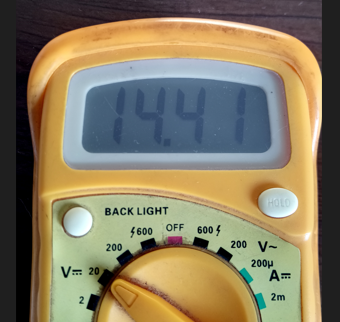
I figured as much. I'm fairly handy with a soldering iron and a resistor chart so if I can figure out where these are, I will change them, provided they are indeed the culprits. Yes, trusted multimeter (and cross referenced on the balancer's reading). They were about 12 hours apart - left the system running on battery overnight to discharge. They're in the same calibration section in the manual. It seems to be an additional optional calibration step, perhaps for accuracy. CF11 turns on both fans (to full, since they're either on or off), then you tell the inverter what voltage you get with these turned on, by using the PBFnnnn command. Presumably this is because they would draw a little more, but realistically I've never seen the voltage drop when the fans are turned on. Interesting however that you've found the additional "percentage" option on the CF command. This is not described in literature, and presumably without any components to control speed, this would actually do nothing. I suspect the inverter may parse the "nnnn" values and ignore "mmm". In any case, the CF and PBF command pair were always a last step I took and never seemed to have much effect on the reading. Edit: As expected, CFnnmmm does nothing extra. CF11 = both fans on, CF00 = both fans off. No fan speed control. Sending CF11050, for example, still turns them both on to full. This whole saga has really drawn out for me and I'm no closer to finding any particular pattern. For instance, yesterday when I woke up the inverter was severely under-reading the voltage (reporting 27 or so), while the batteries were being pushed to a dangerously high 31.10... Once again, I started with PSDF, used 31.10 as the PBATH reference, then left them until about 26.50 for the PBATH reference. PSAVE, CF11, BPF, and so on... It got rid of the overcharging, but still remained inaccurate. Throughout all this, the SCC voltage has been easily and reliably set to an accurate reading. It's the "battery" voltage that always drifts, and it is this voltage that the inverter uses as a reference for the battery SoC, charge voltages, etc. Hence, when it is wrong, everything is wrong. I've just done yet another PSDF followed by the usual steps. This time, however, I issued a PMID directly after PSDF. So far, I'm closer than I've been in a while: I measure single battery voltage for better accuracy on the meter. Fingers crossed this does not drift again in a few hours or days... I suspect PMID is a black magic command that does a lot more than we know. Perhaps it must be issued after all? I know @Coulomb you suggested not to issue it, and I have avoided using it, just sticking to PSDF and the PBATH/PBATL pair, until now again. There is probably also a correct time in the sequence to use it - be this directly after PSDF or after the voltage pair. The hunt for accuracy continues...
-
jbroo reacted to a post in a topic:
Synapse (Voltronic/Axpert) battery voltage calibration - help?
-
jbroo reacted to a post in a topic:
Synapse (Voltronic/Axpert) battery voltage calibration - help?
-
Thanks @Coulomb I think the resistors you speak of must be intermittent or toast. Pity, the machine is less than a year old. I tried last night/this morning, leaving the batteries to drain: PSDF (ACK PBATH2648 (ACK PBATL2256 (ACK CF11 (ACK PBF2244 (ACK PSAVE Sadly, the result is still way out: QPIGS (225.0 49.9 225.0 49.9 2460 2459 102 423 26.86 000 100 0031 0000 000.0 24.75 00000 10010101 00 03 00000 100
-
jbroo reacted to a post in a topic:
Synapse (Voltronic/Axpert) battery voltage calibration - help?
-
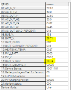
Hello all. At some point my inverter decided to de-calibrate itself, so now it is wildly over-reading the voltage, and consequently not charging the batteries. I've played ad nauseum with the PBATH and PBATL command pair, and have established I can pretty reliably set the battery voltage on the SCC, however this doesn't come into play - I don't have solar and this reading does not seem to influence the inverter's actual perception of the battery SOC. Instead, it uses the "battery voltage" reading, which I cannot for the life of me seem to set in any way. For example, these commands reliably set the SCC voltage (even when using the same voltage reading): PBATH2458 (ACK PBATL2458 (ACK PSAVE (ACK This results in the following: Battery voltage 28,71V Battery voltage SCC 24,58V QPIGS result: (228.0 50.0 228.0 50.0 0374 0338 014 418 28.71 000 100 0027 0000 000.0 24.56 00000 10010000 00 03 00000 000 Note the correct SCC voltage set above, and the wildly incorrect "battery voltage". I've done this over and over in various permutations, with/without PMID, with/without a power off and on, with/without CF11/PBFnnnn, and so on. I've figured out how to set the SCC voltage accurately repeatedly, but the other voltage just does not correlate, ever. It's gone as high as 30+V, and as low as 24, with no relation to the actual battery voltage as measured by a multimeter, nor any relation to the value displayed for SCC voltage. Any ideas here would be greatly appreciated. I'm sitting with flat batteries that won't charge until this stupid thing actually knows they are flat. @Coulomb maybe you have some suggestions?
-

Fair pricing for a Battery/Loadshedding backup without Solar
jbroo replied to Sam11637's topic in General Discussion
I paid 15.5k last year to install my solarless backup solution. 3kva inverter with 2 x 200Ah LFPs. Price included all materials, steel battery box and COC. For proper work, this seems to be the going rate. -
 jbroo reacted to a post in a topic:
SunSynk WiFi Dongle Hacking.
jbroo reacted to a post in a topic:
SunSynk WiFi Dongle Hacking.
-
New software for Inverter/Pylontech monitoring and control
jbroo replied to yani's topic in The Internet of Things
I just saw version 1.18 was released here. Tested and working well. Pity this is only Windows based. -
Zerotier works great for me.
-
what device will regulate the voltage to a steady 230 v
jbroo replied to bony999's topic in Accessories
And finally maybe this: https://za.rs-online.com/web/p/power-conditioners/7079851 -
what device will regulate the voltage to a steady 230 v
jbroo replied to bony999's topic in Accessories
Also this: https://za.rs-online.com/web/p/power-conditioners/7079839 The current draw/passhrough limitation is likely to be an issue however. -
what device will regulate the voltage to a steady 230 v
jbroo replied to bony999's topic in Accessories
Generally used in audio and music studio contexts, but a power conditioner may do the trick: https://www.furmanpower.com/stable-power-regulation/ https://www.furmanpower.com/220-240-volt-region-pro-av-commercial/