Ivan_E
Members
-
Joined
-
Last visited
Everything posted by Ivan_E
-
A massive thanks once again to @slipx who delivered the goods. Now working like a treat. 👍
-
@p_i Hi Can I confirm you formula is correct please? second = register24%256 minute = (register24-second)/256 I seem to be calculating the minutes using this register24%256 for example Int(5165/256) = 20 However I don't seem to be able to calculate the seocnds correctly.
-
-
@p_i I get the year but I am struggling with the 6147 % 256 = 3 sorry 😳
-
@p_i So I am trying to get my head around working out the numbers into a readable form, So for example how does 6147 work out to be March 2024? I can see your notes but how does this break down as I am learning as I go? month = register22%256; year = (register22-month)/256+2000;
-
Hi Shaun, that is the idea to use HA with the help of ESP Home but unfortunately the registers I am looking at are a bit more complex and haven't been covered before as far as I know. I need to work out how to interupt the numbers I get from the register before I can write them back. This is all new to me so it's not exactly second nature.
-
I too am using Node-Red as HA automatiion is too limited. Let me know how you get on please as this will been good to implement.
-
In the UK but this forum as been a great help. Currently running a SunSynk 5.5kW inverter and with the outage of SunSynk in the UK over the weekend it messed up the Time Sync on the inverter. So I looked into it and believe there is a way to sync the time with an external source via an ESP32 / RS485 to TTL board. I have found out ModBus registers 022 - 024 see to be labelled as System Time. (ModBus.jpg) I exposed these via the ESP32 board but (HA Entities.jpg) But looking at the numbers in eahch screenshot they make no sense, (Day Hour.jpg \ minute second.jpg and year month.jpg) Anyone know how to convert them to a human readable format and also I assume as they are R/W these can be adjusted on the fly? Maybe someone has some experience with these? Thanks ModBus.jpg HA Entities.jpg Day Hour.jpg minute second.jpg year month.jpg


-
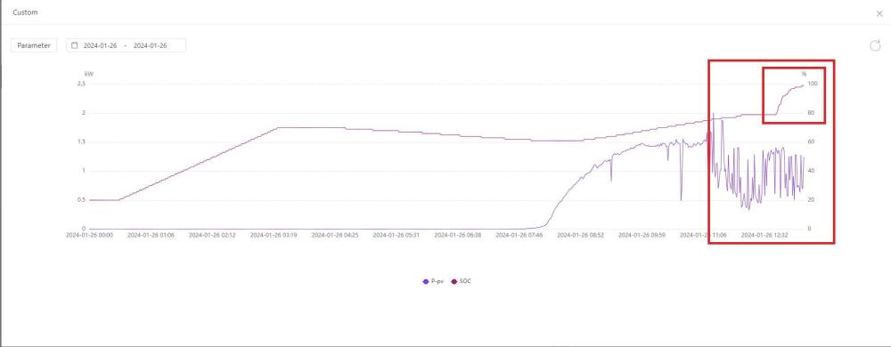
Thanks Buyeye, I did indeed kick off a 100% charge last night so let's see if the drain is fairly linear. Thanks
-
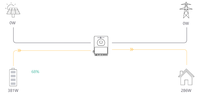
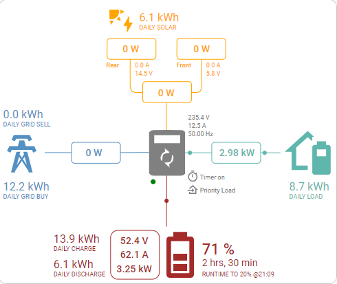
Hi All, UK based person here. I have noticed today the SOC on my 3*SunSynk 5.32kWh batteries have jumped from 79% to 99% in the space of 25 minutes. I have no charge timer on and solar is only delivering 1.5kWh of power (Winter in the UK, actually winter pretty much all year round compared to SA 😆). Now I highly suspect they are out of balance as the charge indicator one of the batteries at 30% is 4 indicators and the other 2 are are 3 indicators. So whats the optimum way to balance all the batteries? Force charge to 100% then dicharge to 20% then force charge to 100% again? First picture is the SunSynk app and the 2nd is Home Assistant with direct comms to the inverter.. Regards Ivan

-
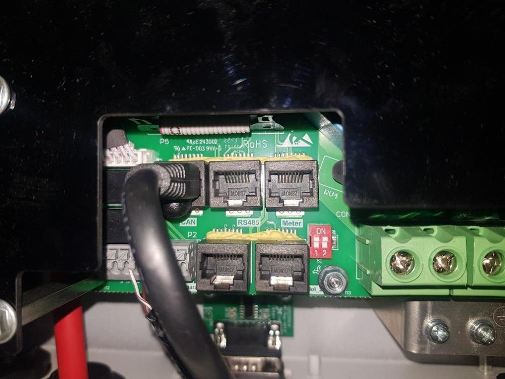
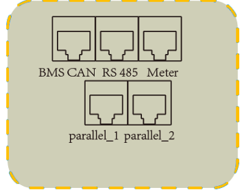
Hi All, Well I have found the issue with my inverter and finally have it working with Home Assistant. If turns out there are 2 * 5.5kW Ecco inverters in the UK. One has the conbined BMS \ CAN port and my 5.5kW inverter has the CAN and RS485 port which are seperate (Ports.jpg) Now on the RS485 port you can not use pins 1 + 2 for RX / TX, you have to use ping 1 and 7. You can see why on this photo when I got a flashlight behind the connection board. (Track.jpg) Once I wired up Orange\White to B- and Brown\White to A+ (rj45.png) and altered the ModBus SN from 0 to 1 (Inverter will require a reboot to get rid of the error) I was able to pull data from it.


-
Caswell, what is your inverter?, mine is the 5.5kW Ecco and I am based in the UK but I am sure that this inverter doesn't have pin 1 and 2 going anywhere on the CAN \ BMS port only the CAN pins are connected.
-
Yes region 2. Thanks for the update Gary. SunSynk servers are not stable at the moment from posts on other forums. Appreciate all the hard work you are doing with this product. 👍
-
Hi all, been using the integration and it's been rock solid, however and this maybe what you were referring to @Gary Waterworth the integration seems to be behind, I am using this in the UK and the clocks have just gone back so not sure if this has any effect? For example here is the website And here is the integration Notice the battery SOC? Regards
-
Has anyone had this working on a new SunSynk 5.5 Ecco inverter in the UK? Here are the ports on the UK 5.5 Ecco. I've tried the BMS \ CAN connector and RS485 connectors, I am begining to think that the UK versions do not have the correct pin outs on the BMS \ CAN bus and the RS485 port on the inverter may have a different pin out compared to the BMS \ CAN.
-
Ah OK, if I am seeing Errors like this [23:46:01][W][modbus_controller:113]: Duplicate modbus command found: type=0x3 address=154 count=1 [23:46:01][W][modbus_controller:113]: Duplicate modbus command found: type=0x3 address=160 count=1 [23:46:01][W][modbus_controller:113]: Duplicate modbus command found: type=0x3 address=164 count=1 and [23:46:05][D][modbus_controller:032]: Modbus command to device=1 register=0xA0 countdown=0 no response received - removed from send queue [23:46:06][D][modbus_controller:032]: Modbus command to device=1 register=0xA4 countdown=0 no response received - removed from send queue [23:46:08][D][modbus_controller:032]: Modbus command to device=1 register=0xA6 countdown=0 no response received - removed from send queue Is this a wiring issue or sensor issue please? Thanks Ivan
-
Hi George, Are you running a sunsynk 5.5 inverter and trying to get the ESP32Dev board and TTL>RS485 board working? I am almost there but I am seeing in the logs Errors like this [23:46:01][W][modbus_controller:113]: Duplicate modbus command found: type=0x3 address=154 count=1 [23:46:01][W][modbus_controller:113]: Duplicate modbus command found: type=0x3 address=160 count=1 [23:46:01][W][modbus_controller:113]: Duplicate modbus command found: type=0x3 address=164 count=1 and [23:46:05][D][modbus_controller:032]: Modbus command to device=1 register=0xA0 countdown=0 no response received - removed from send queue [23:46:06][D][modbus_controller:032]: Modbus command to device=1 register=0xA4 countdown=0 no response received - removed from send queue [23:46:08][D][modbus_controller:032]: Modbus command to device=1 register=0xA6 countdown=0 no response received - removed from send queue Are you by any chance seeing the same?
-
Hi Folks, I am well and truly stuck. I have the the setup by @Sc00bs in his video https://www.youtube.com/watch?v=VxhmD2GAJv4", not sure if I have to fully remove this before I start with the ESP32Dev \ RS485 build? I have the SunSynk 5.5kW inverter plus batteries. I have check the wiring and can confirm I have followed this wiring diagram to the letter. I have installed the drivers from the ESP website and can see the ESP module when I plug it into my Windows PC on serial port 7. In Home Assistant I add the ESPHome add-on and then prepare the ESP module for initial setup where it joins the ESP module to my Wifi network, this is sucessful, I then click on Adopt in ESP add-on plugin. I then remove the module from the USB port and plug it into a USB powersupply. After a few seconds the Add-on in Home Assistant shows as online. I then add the device in Home Assistant under Device and Services. I go back to ESPHome and click edit, to view the YAML that is installed on the board, I then copy in slipx06's code and change the board: esp32dev, I update the encryption key. I also update as the pins I am using are different from the one slipx06 uses. I also update the fall back SSID \ Password and the OTA password. I then Save and Install the settings and all appears to run through. I start to receive logs but entity values never appear in Home Assistant and they are marked as Unknown. I have download the log Log.txt and noticed there are lots of these [11:07:11][W][modbus_controller:113]: Duplicate modbus command found: type=0x3 address=81 count=1 [11:07:11][W][modbus_controller:113]: Duplicate modbus command found: type=0x3 address=84 count=3 and these [11:07:07][D][modbus_controller:032]: Modbus command to device=1 register=0xBE countdown=0 no response received - removed from send queue [11:07:09][D][modbus_controller:032]: Modbus command to device=1 register=0xF3 countdown=0 no response received - removed from send queue Is this normal? I've also noticed when I push the code down it displays a warning about using Pin 4 for flow control, again is this normal? Regards Ivan

-
OK so I have the 5.5kW inverter and I have also change the board to the one listed. I have wired it up like the diagram and adjusted the following config based on the PINOUT diagram, I am much closure but not yet across the line. I can see lots of logs coming out the ESP32 unit now which is a step in the right direction. uart: id: mod_bus tx_pin: GPIO17 rx_pin: GPIO16 baud_rate: 9600 stop_bits: 1 modbus: id: sunsynk_modbus flow_control_pin: GPIO4


-
When you say the rest of the YAML code, which part are you referring to please?
-
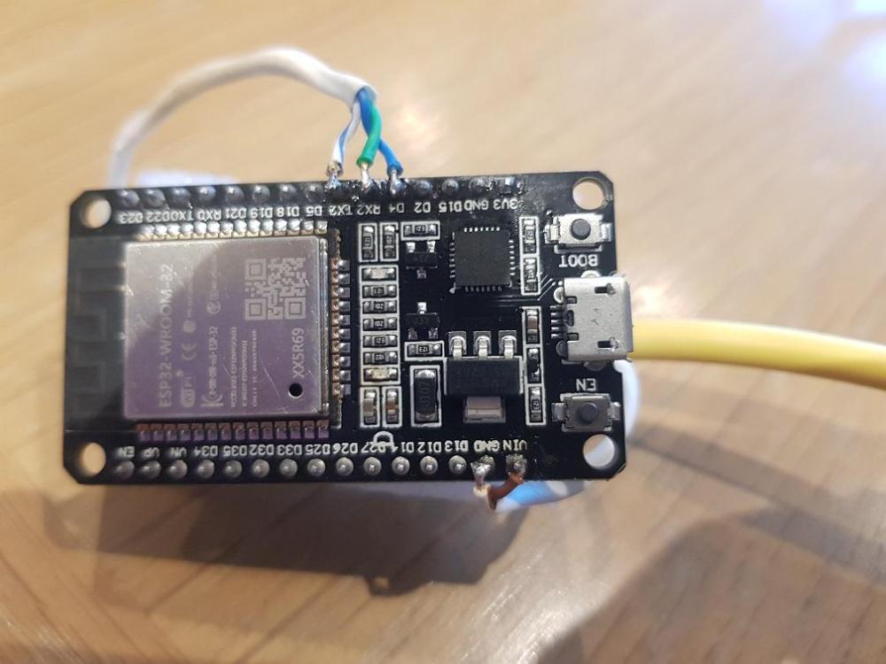
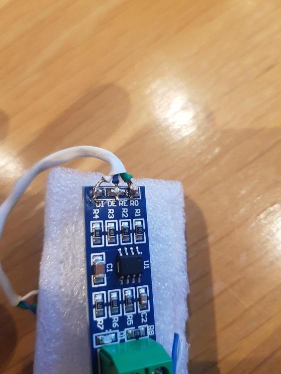
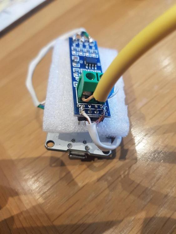
Hi Folks, Been building the ESP32 and RS485 project up to connect to an inverter (I am UK based). Anyway bought an ESP32 DEV board and this TTL > RS485 board I've wired them up as described and followed the instructions. I can now see the ESP board in Home Assistant fine but when I click on it there is only 1 entity which is "ESPHome Web 137a18 Firmware". I have tried the following: Removed the R7 resistor Tried a second TTL > RS485 board Tried a second network cable Reversed the network cable wires that are in the TTL > RS485 board Remove the plugin fully (Including removing the old directory left) in Home Assistant Flashed the board a few times. Re-seated the RJ45 into the inverter Reheck and re-soldered the wires again When I check the logs I only get a few lines around the setup see the attachment INFO attached ESPHome 2023.7.1.txt (I have hashed out the MAC), there is no data coming from the Inverter other than the output. I am not sure what else I can do. Any help I would be greatful. Regards Ivan INFO ESPHome 2023.7.1.txt