


luk88
Members
-
Joined
-
Last visited
-
-
Thank you for the reply. Sadly I was mistaken . It is not the inverter. The preamp for the SDR I was doing the testing with was powered by the inverter so the signals dissappeared when I switched it off. Imagine my surprise when I disconnected the inverter ,put it on my bench. I put grid AC on the line the inverter was powering and the noise came back... So the thread is a bit pointless now.
-
I'm hoping someone can help me with so.e tips what to check as I can't really afford to buy a new inverter because of this. I have two of these inverters and only one is jamming both the CB and the 10m Ham radio bands in the entire neighbourhood when the AC is on. When it is charging the batteries from solar it is fine. When it it powering loads it is even worse. So I know the problem is with the AC inverter module. I'm pretty goid with digital electronics and general repair, but I never dealt with such a problem . To summarise, with the inverter off my RF noise floor as seem on an SDR is about -80dB. The moment I seitch the AC on it suddenly transmits huge signals up to 40dB over the noise floor (up to -40dB jamming even the strongest signals). Mostly at 10Mhz, 5Mhz, 20Mhz and then the worst. A continuous chunk between 24Mhz up to 44Mhz of spikes every few tens of KHz raising entire noise floor up. Do CBs and Ham radio in 10m bands are basically unusable here. @BritishRacingGreen @Coulomb maybe you have some tips? The other inverter of the exact same type generates nothing. What parts would you suggest I check first?
-
 luk88 reacted to a post in a topic:
Does anyone know why certain inverters work fine with small/cheap AVR generators and others don't?
luk88 reacted to a post in a topic:
Does anyone know why certain inverters work fine with small/cheap AVR generators and others don't?
-
I saw few mentions that this or that inverter works or doesn't work with cheap AVR generators. All inverters I saw manuals for (Voltronic clones mostly) claim acceptable frequency from 43Hz to at least 63Hz which is a very large range. I see no max THD mentioned anywhere. Does anyone know how to predict a certain AVR generator will work with a certain inverter? Before I even knew about this problem I helped my friends build their tiny system with just 400W solar, single 12V 100ah battery, a 1kW all in one inverter and a 2-stroke petrol generator. They haven't had a problem with the generator until the carb clogged up and started surging. And that is both one of the cheapest inverters and generators I ever saw. Now I've recently bought a new generator, but it will be a while until I can connect it to my system (but I only have 14 days to send it back if I find something I don't like) so I wonder if there is anything I can do to determine this in advance. My generator is a Chinese diesel 9500W (same line of products as this, but with 195FE engine and 7500kW alternator). My inverters are Easun SMH-7k (similar to Voltronic Axpert MKS V) and Y&H 10.2K (also known as PowMR, perhaps Axpert King? I'm not sure).
-
Youda reacted to a post in a topic:
Inverter lying about power in Watts, but reports correctly in VA.
-
I'm not seeing the screenshot, but my unit also hasn't got the information about AC input power. Both on lcd and via the rs232. I get load power on AC output, but there is no way to see AC input (in consumption or export). Do you have the right cable? I don't know the pinout of Seplos BMS, but I know the inverter's rs-485 plug uses first two pins of rj45 only. I believe pin 1 is A and pin 2 is B, but I'm not 100% sure it is not swapped. These are the pins that are usually white-orange and orange in typical straight Ethernet LAN cables. There is another standard where these pins are white-green and green. You can tell which you have by looking at what color is at the edge (white-green or white-orange). Comms wise, the inverter runs at 9600 and it has 3 protocols to choose from. I'm using pylontech (with own software battery emulation) but there are two more to choose from. If you can find the BMS pinout and to set it to 9600 bps perhaps it will work with one of the three. Maybe the BMS has a protocol choice too?
-
Hi, I have two of these, sorry I have no time to read this entire topic now, but let me say both of my inverters are working fine. However, when I got them initially I made a mistake of connecting both PV1 and PV2 in parallel to the same large array and back then it was behaving exactly like you describe. I didn't realise this model has two independent MPPTs and not just a single MPPT with two sets of leads (like some earlier models did). So once I've started using pv1 and pv2 as independent MPPTs it works fine. On the lcd I do get information for one or the other. It cycles depending on up/down press. VIA the rs232 (both the dessmonitor and my own software) there is only voltage for one PV input and total PV charging power available. There is no voltage on another pv input and no "amps per pv input". That is honestly not a big loss, because it is so horrible in measuring current (reporting 7a when there really is 1.5A) that the lack of it is for the better.
-
Ok, I've done more testing... Including with different meters. And I have to say the reality much worse than I expected. For example both of my 10.2kW inverters consistently report over double the current on the PV inputs when it is fairly low. For example. Today (during a very rainy day) I observed the current be around 0.5,0.8A solid. Inverters were consistently reporting 1.6A~1.8A. I never noticed any discrepancy when the current reaches the top limit of the input. Same, but even worse happens on battery input, but here one inverter was a lot better than the other (maybe because one was pulling from the battery and the other was charging?) . The one that was discharging only had about 20% error at ~6A. But the charging inverter was only pushing 1-1.5A into the battery, but it was reporting 7A! This is insane. Since I deployed my system electricity was seemingly "escaping" somewhere. Now I know it has not been escaping. It was being measured very badly. Can someone please comment if this is normal with 10kW voltronic clone inverters? It is as if they are adjusted to measure high range of current at a cost of horribly inaccuracy at low range. Does everyone use external sensors? If so, can someone suggest some hall sensors for the pv? (as precise as possible current up to 30A) Also kwh meters for 240V AC that take into account power factor in their measurements and are easy to get data from? (preferably via local WiFi or serial).
-
I thought I replied after @Coulomb's post, but I must have forgotten to hit submit or something, because I'm not seeing my post... It is second nature to me, but no need to apologise, it is a very valid point 🙂 I always hit a button marked Ref. I also do it right next to where I'll be doing the measurement (before clamping on to the wire) to avoid the possibility of somthing nearby messing with the reading. Interesting and very good to know. I also don't trust my clamp meter that much, but I have 3 inverters hooked up to the same bank of batteries so I can only see combined current on the batteries (on the batteries side I have a Victron Smart Shunt to measure the total and each battery in the bank has its own BMS). I too would prefer self consumption to be included, perhaps the best would be a menu setting, we can wish... Yes, I wonder how precise the SmartShunt really is. It is supposed to have 0.1A precision. At 500A maximum. I have to compare the data with my BMSes, but then which do I trust? It's like in this saying, a man with a watch knows the time, a man with two watches is never sure.
-
Youda reacted to a post in a topic:
Inverter lying about power in Watts, but reports correctly in VA.
-
You are exactly right. Thank you 🙂 I record the data from my inverters via modbus (a small script I wrote that reports to MQTT, from there it goes to homeassistant and grafana). I got the register numbers here https://github.com/odya/esphome-powmr-hybrid-inverter/blob/main/docs/registers-map.md and they are indeed swapped for VA and Watts. I rarely go to where the inverters are installed in person, but the other night (when there is no load at all on that inverter as only things it powers are washing machine, dishwasher, microwave etc, appliances I know are off when everyone is asleep) and I saw it was reporting about 300VA and almost no Watts of power. So this solves that mystery. Now I have another one... The inverter is supposed to consume 75W idle power (not ideal, but not horrible either). I also measured DC power drawn at the same time(using a DC clamp meter set to 40A) and I saw 2.3A (at 53V). To me this seems pretty excessive. 75W is 1.4A at this voltage. It is set to appliance mode (I heard these inverters consume more in UPS mode, because it has to be always in sync with the grid.). But also I noticed it is in almost perfect sync with the grid when in battery mode even set to appliances. So perhaps this software just pretends to switch to appliance mode? What do you think?
-
luk88 reacted to a post in a topic:
Inverter lying about power in Watts, but reports correctly in VA.
-
Hi, one of my two 10.2kW Y&h inverters (some Voltronic Axpert clone also known under PowMR, Sumry MPS VIII Eco and other brands) is lying about the load power. It is showing 300W load power even in a middle of a night (in battery mode) when nothing is using it. The battery current going in bounces between 0 and 1A so I know it is really only on self consumption of up to ~50W (this is at 53V battery voltage). At the same time Load VA shown much more realistic value that bounces between 18VA to 60VA. I thought perhaps it is some current sensort/transformer, but wouldn't it use the same CT for measuring output current as one used for the VA calculation? My second unit is much better, but still it's load Watts seem 50W too high. Does anyone know if there is some way this can be corrected by setting some internal potentiometer or replacing resistors perhaps?
-
luk88 reacted to a post in a topic:
3-phase with 3 standalone(no connections between) all in one inverters?
-
Yes, they are. I didn't think these details were relevant, but for the sake of completness I'll add more 🙂 I have 14kW peak PV array, but due to max current limitations and the way it is connected it operates at max 9kW peak power (I'm mostly concerned with low light production during rain/winter - I have too much electricity during summer anyway. I currently have 45kWh of battery storage (considering adding 10kWh more as I already have the cells, but they are very bad quality cells so I'm reluctant). This is a single system with 3 hybrid inverters, but not parallell. All inverters are connected to the same battery, but they power different loads. 2 inverters (Y&H 10.2kW) have each half of the array connected to them. The third inverter (EASUN SMH-ii-7k) has no PV currently. All have grid connected (each one has a different phase) and all work in SBU mode. All are configured to charge from the grid only if the battery voltage drops pretty low (which I hope will not happen during the most of the year). There is a transfer switch and a small gas generator (3kW) that can be manually connected to the EASUN inverter to charge the battery if the grid goes down for a long time in winter. I also have a separate purely on-grid single phase system for selling power to the grid. This has a Deye 3kW inverter and 2400W of panels. This system paid for itself in the first 3 years of operation (as I got the panels from a bankrupcy sale and I made the ground mount myself), but the cost of electricity here in Europe is insane now (3x what it was 3 years ago). So the purpose of the current system is to use the grid power as little as possible and where it is inevietable use power "saved" by the on-grid system (although due to recent changes it makes less and less sense to sell power to the grid). The house consumes 10-20kWh per day depending on season and how much we want to save. Everything is electric. The geyser has no tank at all (it is a wall mounted unit that regulates water flow based on set temperature, we set it at 50C) and one can have a normal 10 min shower using only about 1.5kWh of electricity. However when one is not paying attention it is easy to use 5kWh in one use. It is not a lot in the grand scheme of things. But its "the last thing" on the grid in my house so I'm looking into how to switch it too. I'm also considering running the heaters on 240V instead (3 separate phases), but I'm not sure if it will be easy to switch and if it'll work (its a "smart" heater so it may detect the voltage and refuse to run). I'm also thinking about adding an outdoor burried underground tank of hot water, but the cost to do that will be quite high as if I was doing such a big job I'd want the tank to also be used for storing house heating water (I already have a heat pump, but it is currently only used for cooling the house during the summer).
-
This is not the case. I checked with an oscilloscope. Each inverter synchronises to each own phase from the grid when the grid is on. When grid fails it continues running with this synch, but quickly drifts. So this can be used only for "off grid with grid backup" situations. If it works well one can imagine a tiny 3 phase inverter providing the sync signal for a 100% set up. But its just an idea. There is no comms between inverters (other than my monitoring). They balance loads/PV/battery without any concern what other inverters are doing (to satisfy their each inputs/outputs). Indeed, that's how it looks like. My only reservation is that normally currently flows between live and neutral output. But in a balanced 3 phase set up current flows between phases only. So lets say there is a resistive load (my geyser) and it is delta connected (or star, but fully balanced). Then there will be current on phases, but no current on neutral... But the current has to get back somehow! So what would happen? So this is my only reservation and the reason I haven't tried just connecting it yet. This could be resolved by a relay (to switch off if grid fails) as another user mentioned. Let me add, this is for purely a resistive load. I'd be reluctant to run inductive loads like big motors with this. I have no space in my home for a hot water tank (so I have to run tankless) the geyser is the only load I has to leave on the grid. On the other hand buying a 3 phase system for one load and spending 3x the money is something I decided against.
-
There are inverters designed to supply 3 phase power. They are connected together and they sync their waveforms by communicating with eachother. This topic is not about tyese. No. I'm talking about the cheap inverters like EASUN SMH-ii (most likely an Axpert MKS II clone with no parallel board). I've done some benchtop testing and I noticed they they sync to the grid exactly even when in SBU mode. So let's say one has a stable 3 phase grid and 3 such inverters that sync to all 3 phases. Can anyone think of a reason why one couldn't use a resistive 3 phase load connected in delta configuration? That resistive load is a tankless water heater (geyser).
-
Or enjoy your free electricity from the grid.... Pity it happened now once you have your own system.
-
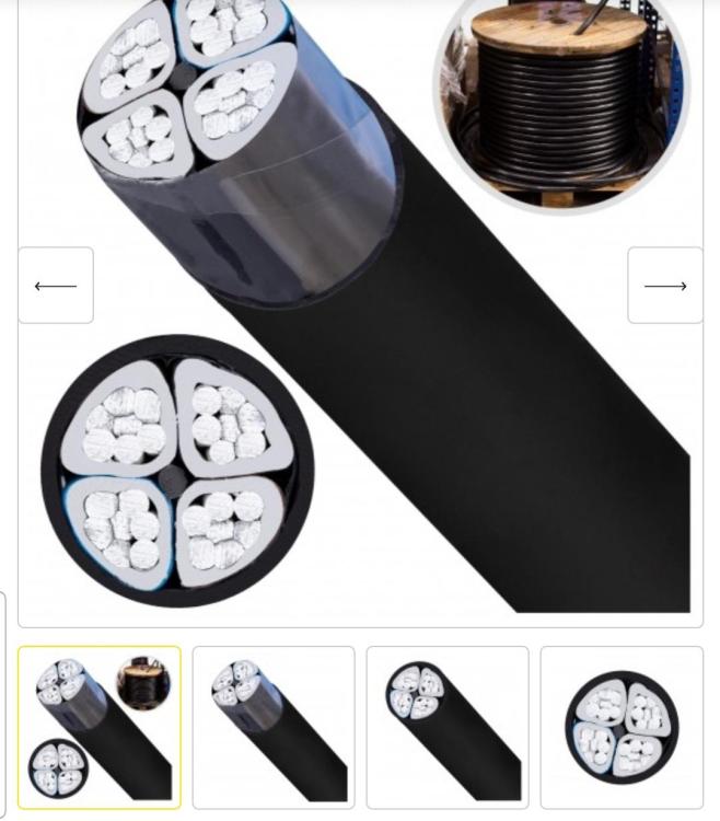
Personally I'd invest in a thicker grid cable. For example (if you currently have up to 40V drop with 110m of 7mm2 cable - this is 75A of current): - with 16mm2 copper (around $1100 here in Europe) you'll have 17V drop, perhaps it is acceptable? You would still be loosing almost 10% of power on cable losses. - with 25mm2 copper (about $1700 here) the drop would be much better at 11V - loosing about 850W of power in the cable Do you have access to cheap aluminum ground cables? If I was in your position and I wanted to use the grid I'd probably buy aluminium ground wire 4x50mm2 (this is 50 fifty square mm, not five) like this For the cost of $700 and the voltage drop will be 9V peak. Then you have to bury it of course and you still have the cost of electricity and possibly uncertainty over supply. But it is by far the cheapest outright and easiest option IMO.
-
-
luk88 reacted to a post in a topic:
ATESS 100kW HV inverter, 2 x 40/32 FreedomWon HV batteries & 40kW PV Array
-
I was almost certain of it, but when you're repeatedly told otherwise one may doubt. This is an interesting take. Perhaps it was the original intent of the manufacturer. I meant paralleling only the battery connection. Perhaps I should've clarified, but I thought it is obvious as I said in the first sentence of the post: However most people when they talk about "pararelling" mean connecting battery and loads together (or setting up loads as synchronised phases). In this sense you're of course right. Coming back to paralleling-only-the-battery side, unsurprisingly it works fine. I've since connected and tested it in all modes. I plan to resolve the charging issue in the short term by having only one inverter have higher bulk charging voltage than the others. In long term by settings up a "fake bms" connection to all inverters.

