Dragan100
Members
-
Joined
-
Last visited
-
-
-
-
-
Hello @Coulomb and thank you for your reply, I found a replacement for the Cout WIMA MKP4F 4.7uF/350VAC, installed it and tested the operation. It responds exactly the same as before with the original Cout, also after a certain time the output LC filtration starts to be noisy/"start singing". So the problem is most likely in the DC/AC drive. Later, I was busy with other work, so the inspection of the Inverter remained on the second plan, and I did not work meanwhile on this topic. I need to bring an oscilloscope to look at OUT 230VAC Sine wave form and DC/AC drive signals, control voltages, analog and logic (+5VDC for logic, +/-(6...12)?VDC for analog...) Meanwhile, I found a similarity of PCB construction in MPP PIP 3024HSE (3KW/24V, 50A PWM) model in some videos on YT. Flyback power supply section from BAT (like in yours SCC3.png) is copy-paste in this EASUN SPS3KW/24V/50A, also analog part with several TL074 around primary MCU, Opto ISO 350 + Floating power supply for drive IGBTs, placement of PV Charge section, heatsinks (find attach. in one of my previous posts) Best regards = Lepe pozdrave = LP Dragan
-
-
I found some micro cracks in the joints on PCB around the 230VAC OUT filter, on Lout and also on Cout (picture attached). Then I re-soldered some larger joints on that section, reassembled everything back, connected LAB PSU 26VDC 10Amax (current limitation), No Grid, NO PV, for LOAD 100W Light bulb only. Switching ON, everything OK! Firmware MCU display [U1 04.23] and for U2 no data on display? Funs do a StartUP check up, then they are in standby. Without load, the Inverter has its own consumption of around 28W (LAB PSU display). With OUT Load 100W light bulb => aprox. 125...130W is displayed on the LAB PSU display. Output voltage 228VAC steady. After about 20...30 minutes a fuzzy/sizzling noise starts to be heard, with the Inverter cassis open I try to locate the source of this fuzzy/sizzling noise! 230VAC OUT section,the output capacitor of the LC filtration OUT 230VAC starts "singing", a little later the output voltage starts to fluctuate/swinging from 180VAC... to 280VAC and back! Consumption during this swinging OUT voltage increased from the previous 130W to almost 200W. I do not have an oscilloscope at this location, so I cannot provide some oscillograms at this time. I have to unsolder OUT C 10uF/350V, measure it, looks good and see what quality it is! I will try to find something suitable for replacement/test 5...12uF/400V (275VAC...440VAC), lead speacing /pitch 48mm or 33mm holes distance on PCB , what type of capacitor do you recommend I mount for this 230VAC LC filtering Cout? Cout for AC filtering, Grid interface, High current peak capabilities, UPS, ... WIMA MKP 4F series EPCOS-TDK B3235 series , B3275 series Panasonic EZPQ series KEMET C4AF series Vishay MKP1847C series


-
Hello @Coulomb and thanks for the reply, at this moment, the Inverter is already completely disassembled, so I will be able to give the version of the main and secondary firmware only when I reassemble it back. The Inverter has two processors, an MC9S08AC60 (NXP?) mounted on the MainBoard, surrounded by a handful of TL074 opamps for ADC controlling inputs, and another M9S8AC16CG (Freescale? NXP) on the auxiliary small vertical mounted board. I am now patiently examining the elements and soldering joints under the microscope, I will report back when I find something. Everything looks OK so far! However, it is definitely very difficult to detect/locate an error that appears after several hours of undisturbed/normal operation! LP Dragan


-
-
The interior looks like new, everything is clean, no dust, 🙂 !!!no additional smell that would cause concern!!! FANs are clean, normaly functioning! Tomorrow I will start disassembling everything out from the chassis, so I will have a better overview of the elements and the quality of the soldering. Most likely, I will also dismantle both heat-sinks, later when reassembling I will also give the Mosfets-IGBTs a coating of new thermal paste. A thorough inspections of the elements will follow, soldering joints, PCB vias, tracs...elements->values, mesurements... Will attach some more close looks/zooms photos. Maybe I'll also add some HDD microscope photos if I find any PCB fracture, bad SMD joint(s)... in short, athervise hard-to-see small things without a magnifying glass/microscope. Maybe someone will recognize from the photos which BrandName Solar Hybrid Inverter clone this is? LP<=>BR 🙂 Dragan
-
-
-
-
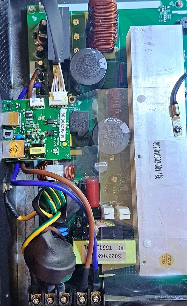
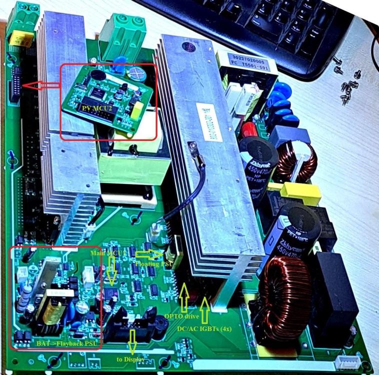
Today I got a faulty [06] Inverter Easun SPS 3KW 24V on my home workbanch. This is what the inside looks like and I made a couple of zooms on certain sections. That's all for now, I'm in a hurry now to get to work!

 Thanks for the quick reply @Shadders, the inverter is 1 year old, it has about 500 hours of Inverter work so far, mostly the complete system is switched OFF, the batteries are charged via PV as needed when/and only when arriving at the location. Only then do switch the system to All-ON. The cottage is located at the edge of the forest, a rather remote location, the cottage is used approximately once a week. So I doubt that the electrolytes are already dried out, but I will still visually inspect/Checking/measure them on the PCB. A friend (the owner of the cottage) checked the inverter's error history yesterday, the Error code 05 ([05 ]Output short circuited or over temperature is detected by internal converter components) also appeared (only once), and that was when the system was connected to the generator set, there was not much PV energy due to bad weather, but used a generator to supplement the batteries and enable the operation of the refrigerator and lights (tot 500Wmax, so it was not Output short circuited , so more likely an Overtemperature fault. As Input Utility, the generator enabled Inverter Bypass mode and additionally charged batteries, solar energy was not available => Program 01 SOL! So here I see a similar problem around DC<->AC , Utility provides Bypass to OUT 230VAC, and we have energy transfer AC<->DC=>DC<->DC=>Charge batteries, so again I suspect AC<->DC IGBT Gate drive problem like @BritishRacingGreen mentioned, not correct/insufficient Gate drive/Gate ON/OFF times, Overlapping ON/OFF Gate times/too short DeadTime due to bad Gate drive/IGBT Id current in FullBridge on one or both half bridges partial current pass through , so I suspect a problem here as well around this Error code 05 like IGBT Overtemperature. Utility charging was set in Program 11 to 15A (insted 25A default), and in Program 02 Maximum charging current: To configure the total charging current for solar and utility chargers, was set to 50A(default for PWM) LP DraganDoes anyone have any idea where to start to locate the faulty board/PCB location, what to check in addition to the already suggested (@BritishRacingGreen) Gate drivers/ON and OFF Gate resistors in DC<->AC inverter section? Until now I haven't even opened the Inverter let alone looked for a faulty area, you know, daily overwork, so that's just coming up! 🙂 And the location of the installation is not at all convenient for me on a daily working basis, so I have to make a "special time" for it! Thank you in advance for any additional help, idea, brain storming... 🙂 Best regards, and LP DraganHello dear forum members, I'm new to this forum, but a E2E veteran/vip/expert member on other electronic forums analog/SMPS/... I happened to stumble here looking for a solution for EASUN SPS-3KW PWM 24V error code 06. In the post quoted above by @BritishRacingGreen, I actually found similar situatioa for Error Code 06, which also appears on the recently installed OFF-Grid SPS 3KW Hybrid inverter (1x) of a friend's instalation in/on the forest cabin (EU SLO Kozina location). The SPS-3KW is not connected to the Grid, 99% of the time it is OFF-Grid, from time to time the 5KVA aggregate generator 230VAC is connected to the Utility input, only when the batteries are almost empty (~down to 21VDC), or when the PV does not provide sufficient energy (consumption 230VAC OUT + BAT charge). The batteries are AGM 12VDC 65Ah each, connected 12+12VDC in series, 3 such pairs in parallel, each parallel branch/line has its own DC breaker, connection cables per BAT line 25mm^2, 1m connection length=> TOT stored energy 24VDC 4.7...5.3KWh depending on the state/voltage of the BAT (22VDC. ...27VDC) PV Inverter PWM input has Voc_max 80VDCmax, for 2KW/3KW model is recommended Vmpp between 30VDC~32VDC, 50Amax TOT PV current, PV Panels are mounted 2x lines {2panels in parallel}, TOT panels is 4X, panels are type 360W @Voc 38VDC, Vmmp 33VDC, I_max 10.5A, and each line in parallel has its own DC circuit braker, connection cables 10mm^2, 6m connection length OK, now that we are familiar with the existing system 🙂 , let's move on to the daily operation, or the subsequent occurrence of the Inverter error. The OUT 230VAC consumption can be from almost nothing, only the Inverter's own consumption of about <30W, to a maximum of 2.2KW. The system operates completely correctly, the PV charges the BAT, or if the consumption is higher than the current PV input energy, it also draws something from the batteries {PV+BAT} for OUT 230VAC. Control parameters on the display are all NORMAL. Error code 06 appears after operation for up to 6 hours of completely regular/normal operation, once for up to 1-2-3 hours of operation, in short the error code 06 appears after a varying amount of regular/normal time operation. The output voltage suddenly starts jumping/swinging from 180VAC all the way to 310VAC and back, there is also a different humming/squealing sound from I assume DC/DC<->DC/AC (trafo, chokes), and later, about a minute-two later, Inverter turns OFF the OUT 230VAC and reports an error code 06, on the display only [06] Then, when I turn OFF the PV DC circ.brakers, I turn OFF the BAT DC circ.breakers, the Inverter RESET, I leave it ALL-OFF for about 10 minutes, later I reconnect the BAT, then the PV, the Inverter starts and continues to work completely normally, of course again it gets into the same error code 06, once in just 10...20min, the second time for about 1 hour into into an identical error! I am attaching the basic parameters of the Inverter, and a link to the Owners manual (13M), latest SW and WatchPower App https://cdn-files.myshopline.com/file/store/2000146714/1625649056137/503c071183fc4e3db5fb03e7c87d1485.pdf https://drive.google.com/file/d/1jniYGEay2u7OsLmtFfff7ryS7Lq2ooLz/view?usp=share_link https://cdn-files.myshopline.com/file/store/2000146714/1625649056137/899150fabe4f4345bcf659125c72614a.pdf sps_3kw_datasheet_en.pdf