Oom Tas
Members
-
Joined
-
Last visited
-
-
I am also running 2 x 5 kW Sunsynk's in parallel and it all depends on the connected PV input power. Say the max PV for Master = 3 kW and Slave = 5 kW When an AC load of say 8 kW is drawn, each inverter will supply +- 4 kW. In this case it will show the the master is discharging the battery, whilst the slave will be charging the battery. The only way for the inverters to balance the load is to balance it out on the 48 V DC side, thus showing charge/discharge. Switching off the PV input on the master the discharge for both inverters will be the same. The master inverter is controlling the whole operation. Comms cable and CT only connected to the Master inverter.
-
-
-
-
Notice this story is now nearly 2 years in the making, therefore I would like to share my non scientific test result. Lots of claims made by Xtend Elements, and they even post flawed test results. Test rig consist of a 50L Kwikot geyser, connected to a 5.5 kW Kwikot Heat Pump. Using the control circuit of the heat pump to display average preheat and post heat temperature. Run the circulating water pump permanently to get a decent average temperature. Temp sensor situated in the middle of the tank. Change over switch to select compressor or element under test, with a Power Meter to monitor the real consumption: Test 1 on spiral 2 kW element: Start at 22 deg C , Stop at 50 deg C, Time taken 63 minutes, Total Power used 2.05 kWh Test 2 on 1.5 kW PTC element: Start at 22 deg C, Stop at 50 deg C, Time taken 74 minutes, Total power used 2.11 kWh As can be seen the results are pretty much the same. The main reason for the slight difference in power consumption most likely the longer run time thus slightly more energy lost through circulation pump and plumbing. Test 3 on 5.5 kW Heat Pump: Start at 18 deg C, Stop at 50 deg C, Time taken 28 minutes, Total Power used 0.751 kWh. I was foolish enough to test all the different type of elements and the results are all the same. The so called bigger surface area of the PTC element makes no difference. The Spiral element surface are in fact greater than the PTC.


-
 Jan.Nel reacted to a post in a topic:
Advice please - Deye 5kW inverter battery settings with three Dyness 100Ah batteries
Jan.Nel reacted to a post in a topic:
Advice please - Deye 5kW inverter battery settings with three Dyness 100Ah batteries
-
Uitstekend. Ek het selwers na die manual gekyk en dit is nie 'straight forward' nie. Fully aggree with GreenFields

-
 Jan.Nel reacted to a post in a topic:
Advice please - Deye 5kW inverter battery settings with three Dyness 100Ah batteries
Jan.Nel reacted to a post in a topic:
Advice please - Deye 5kW inverter battery settings with three Dyness 100Ah batteries
-
Scorp007 reacted to a post in a topic:
Advice please - Deye 5kW inverter battery settings with three Dyness 100Ah batteries
-
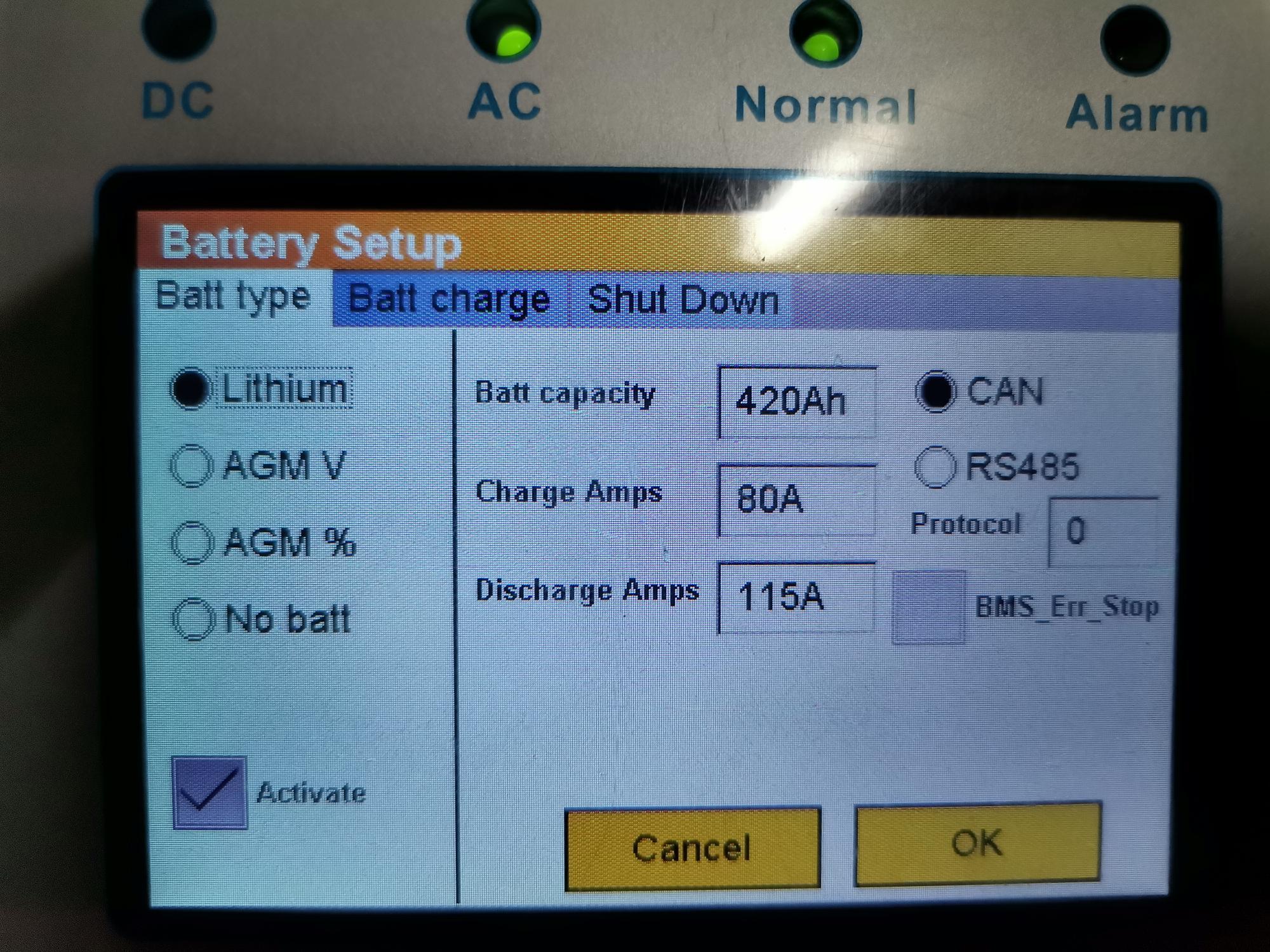
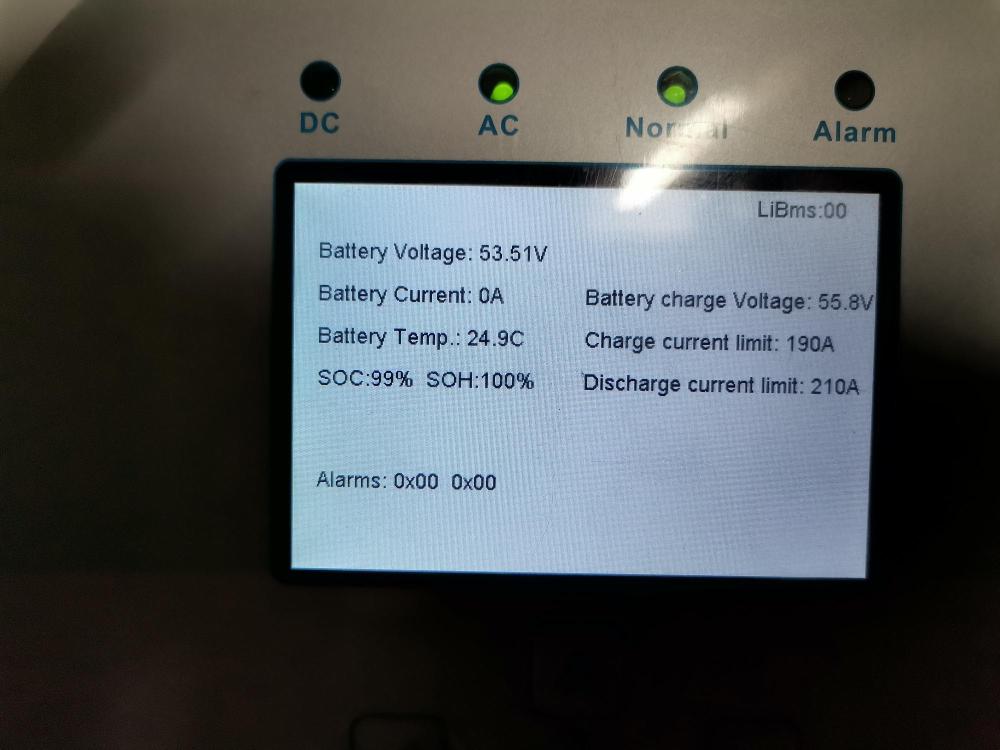
Hi Jan Looks like the added batteries are not in communication with the inverter (see attached pics of mine with 1, 2 and 3 batteries in service) It update the displayed value automatically. Most likely dip switch settings issues.


-
Hi Colin Sorry for the confusion caused, my mistake. When working on 3 phase equipment it is advisable to confirm rotation with phase rotation meter.
-
Lately I noticed that the microwave clock seems to gain time during loss of grid. Further investigation revealed that the frequency increase to 52Hz during load shed. The only setting which match the 52 Hz is under Auxiliary Load, SmartLoad Setup, If selected For Micro Inverter Input, AC couple Frz High. The lowest setting is 50.5 which match the attached screen shot. I am using the output as Aux Load Output for the Geyser. The next step would be an firmware upgrade, as i have done a factory reset with no positive result. Any body else with the same issue?

-
Hi Larry Same problem noted with a UZ battery a while ago. Turned out that the battery rating = 0.5 C Therefore max charging and discharge only 50A. The BMS will simply cut out therefore no data will be logged on the inverter. Only solution is to get a 2nd battery or keep loading down during loadshedding. Q2: Don't think you can change the scaling. At least you can see in kwh Battery IN/OUT Solar Gen Sell and Buy from GRID.
-
-
-
-
Hi razzor13bt The first picture of the 63A DC circuit breaker is correct, if the source is connected to the top of the breaker the right hand side is the positive with the load positive also on the right hand side bottom of the circuit breaker. If the source is connected at the bottom of the circuit breaker the positive must be connected to the left hand side pole and the top of the circuit breaker will be the positive of the load. It is done like that in order for the magnetic blowouts to quence the arc. (Fault current will flow clockwise through circuit breaker in both cases)
-
Hi AC-DC, It simply means phase rotation, clockwise 0/120/240 and 0/240/120 the opposite direction.