Padwan
Members
-
Joined
-
Last visited
Everything posted by Padwan
-
You kinda almost there, as far as inputs for Time, Power, and SoC go fairly straight forward. Actual register(s) holding value for charging state for given time slot on/off requires bit more elaboration.... Albeit if file access permission flag makes sense to you it kinda works in a similar way. Charge field in inverter registry is integer and holds values for, all possible states State table should look something like this : GridChrg GeneChrg 04 false false Both off 05 true false Grid on, Gen off 06 false true Grid off, Gen on 07 true true Grid On, Gen on So if you don't need anything fancy and/or care for states other than grid charge on/off having a simple map that binds 04 to false and 05 to true should do the trick ... I'm assuming rest of the reg addresses and such like you have already worked out. Hope this helps
-
Pretty much all Sunsynk and Deye models use same registers as described in the document. Differences come with wiring pins and getting stable read.
-
Thank you @Youda. This does makes sense, guessing the potential difference would cause voltage fluctuation between them and MPTT's would constantly be adjusting.... kinda like no win wars ... oh and P.S swt setup you got. envious..
-
Ok, great thank you for the input. So ill take from this that in case of multiple PV strings each inverter should have its own combiner box? I'm kind of looking for reasoning behind this, possibly due to my ignorance about some laws of physics. But my reasoning is that splitting battery over the bus bar is similar to splitting PV arrays string via combiner box ?
-
Morning Folks, Been scratching my head about what would be correct way to connect PV with couple of Axperts in parallel setup. Now this sounds trivial, and probably is, but given the vagueness regarding the connection of PV in the parallel installation manual I had to ask ...... Given that the parallel installation manual describes in fine detail with supporting diagrams how to connect AC, Battery and load. But for the PV connection uses one sentence to refer the reader to the single unit installation guide, followed by a caution note that "each inverter should have their own PV cable". Some simple reasoning would be that typically there would be multiple strings connected via combiner box. One could take a separate cable from the combiner box to each inverter. My questions: How does one interpret this section of the manual? Why the vagueness and cautionary note re PV ? Can using combiner box as a "bus" to connect multiple inverters by their own cables be correct way ? ManualParallel-installation-MKS-4Kva and 5kva.pdf

-
@Pipes I went trough similar experience back when i just installed mine, tldr is that you would have to wire specifically outside your inverter to overcome your issue. https://powerforum.co.za/topic/2880-axpert-earthing-issue/
-
@Richyv Ive sourced mine form Armando @ SolarAdvice https://solaradvice.co.za/product/pylon-us3000b-3-5kwh-li-ion-battery/ They do deliver, and have been absolute pleasure to deal with.
-
So far two stores turned up locally https://www.mouser.co.za/Search/Refine?Ntk=P_MarCom&Ntt=116474509 https://za.rs-online.com/web/p/electric-vehicle-connectors/1243948/ Still, bit pricey me thinks..... Any leads to more competitive pricing would be appreciated
-
So connectors are called SureLock manufactured by Amphenol. http://www.amphenol-industrial.com/images/catalogs/SurLok Plus Brochure.pdf Anyone here seen or heard where one can buy few of those? A search turned up a few on amazon store, but prices looked bit high especially shipping and import duties, like 39-95$ for a single connector and 136$ shipping and duties.
-
What would I be risking trading-off by doing so, at the moment my options were to accept voltage on my neutral [and pray this does not cause harm or damage] bond earth and neutral on out terminal in my db board to get rid of the 94V going to my home circuits [this comes with a tradeoff that inverter will not switch over from battery mode, and if it does somehow end up in grid supply (ac input to inverter goes up), my db board earth leakage trips ]
-
So It turns out this is not intermittent. When the inverter is in battery/PV mode, neutral and earth on out terminal give out 94V. When in bypass mode, reading on neutral & earth on out terminal is 0V. So the real question now is, does this behaviour constitute malfunctioning unit or is it simply way [older] Axperts work? [Have to mention that 2 out of three units I've got from this batch/supplier behave the same way, so is this feature or bug? ]
-
I can only make out three of them in there unless smaller grey one is "the fourth"

-
According to my manual and LCD display, there is no option 38, it stops at 31. So I guess that is off the table than for my inverter. Would visual inspection help to identify if this is a model with such a feature? This Inverter is distributed under the branding of "The Sun Pays" and @Coulomb and I had a lengthy discussion about how this "generic" components and ability to custom branding and serial numbers that are not matching Axpert mainline brand and production, create confusion on whats genuine models and what are clones. Especially in light that those units are actually distributed with his patched firmware in place. As much as its fun and gives a great opportunity for learning about this, i'ts starting to feel that i should start making a short list of alternatives that I can use as a primary workhorse and keep Axperts for play and learn. I see you have Victron, any particular combination or model I could add to that list, and any others I should consider? I'm CPT based but on Eskom network, if that plays any role in decision making.
-
how does one validate this, if its present or not?
-
@plonksterWould this help ? Axpert MKS-4000_KS-5000 Service manual. Axpert MKS Charger_ Inverter. Service manual.pdf How does one verify if this is present or not?
-
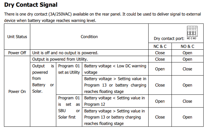
This appears in my manual, how would I test if this dry contact is useful for the purpose of
-
Ive Yes, now it all fits in, and ive confirmed that by measuring in two different states. When in battery/PV mode there is a reading of 94V on the out terminal, bonding E&N on subboard is than necessary to get 94V off there. When in grid mode, its 0.1V, however, have to take E&N bonding away in this case before I can change modes again. There appears to be a dry contact on the inverter, but its labelled PV input and ohm values don't change from NC / NO when going from grid to battery so I guess that cant be used to connect the relay to control bonding. Will go over the link above to see if there are any ideas how to deal with this.

-
So this has just got progressively more interesting. After making a star point in my sub-board to deal with said 94 odd V on the inverters out terminal and everything looked ok. Last night, however, after attempting to switch over to a grid supply, every time there was AC in on the inverter it tripped the earth leakage on my sub-board. So as none of that made any sense, I've decided to experiment some more. Removed a star point from my sub-board and inverter came on, took ac input and did not trip earth leakage. Next was to measure earth and neutral on the inverter out terminal, and it was giving zero reading. Whilst I was scratching my head and wondering what on havens is going on, [5-10 min] I took another reading and it was back to 94V. So star point back on the sub-board and reading between earth and neutral on out terminal is back to zero. So now I'm totally puzzled, does this appear to be a malfunctioning inverter or am I'm missing some profound detail of how this all works and needs to be wired?
-
thx @pilotfish & @Jaws One would expect this to have been done in the inverter already, but I guess that is why some inverters don't make it to the approved devices list.
-
So I’ve discovered something rather concerning. I’ve been trying to trace misterius voltage pulsing trough my house. Fist I’ve noticed some led lights where glowing very dim after being switched off. Which sent me on a hunt of what was putting ~24v onto my lights circuit. Eventually after checking all light switches, dimmers etc. I’ve ended up discovering that my Axpert is pushing voltage even when switched off and disconnected from batteries, but connected to the mains. For now I’ve disconnected inverter from my house supply and running on main grid only. Very concerned about this. Below are readings that I’ve collected on inverter in out terminals. With inverter switched off, main grid connected inverter: In live and neutral 230v In neutral and earth 0 Out live and neutral 0 Out neutral and earth 24V With inverter on , grid batteries pv connected. In live and neutral 230V In neutral and earth 0 Out live and neutral 230V Out neutral and earth 99V
-
looks like 52 is new 42 .... 😮
-
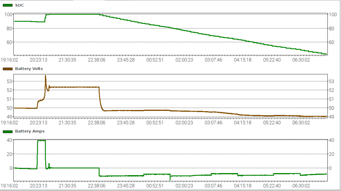
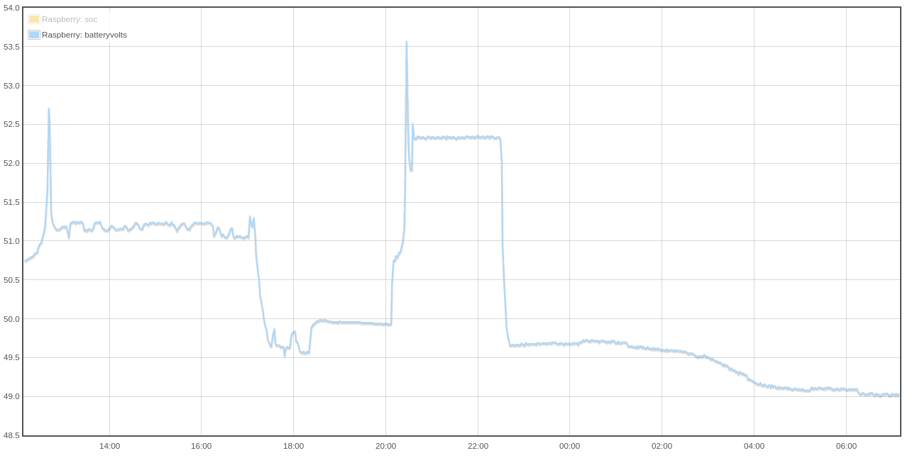
Very similar observation on my end as well, it was reporting 89% than it had a little spike 53.8 and said ok im full now ... Will do thired day of measure before I try @Coulomb suggestion


-
Will certainly test out those values next master @Coulomb
-
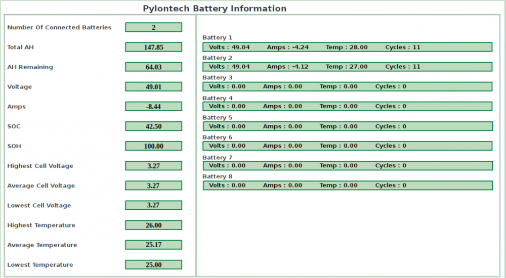
Still trying to form an opinion about this, can only share my observations and data collected so far. After reading your post (very-long-article-about-charging-lfp-batteries) , which was very interesting and informative thank you. I've set to experiment. I'll share some data screenshots for now, and edit to add my observations. tldr; it appears that most productive values for me where in that 52V range.



-
Hello, I'm looking to connect 4-6 US3000B type batteries in parallel, however, space I have available in my location is narrow but long. I can fit at most two upright and then add an additional pairs to the side So I'm looking for a custom cable length that will have compatible connectors that would be long enough, 30-50cm, to allow me to arrange them in the following orientation. 1st Pair 2nd Pair 3rd Pair ______ ______ ______ |____| -> |____| -> |____| ______ ______ ______ |____| |____| |____| Any ideas if this would be possible and where would one look for such cables length. Alternatively, any suggestions if those connectors are some standard type I could purchase separately and custom make the cable length I require.