kuba.cz
Members
-
Joined
-
Last visited
Everything posted by kuba.cz
-
I'm not sure about that as I have no experience with Pylontech batteries. The JK BMS does have all the ports that the original card has, including the RS485 "link" ports for connecting to other batteries in parallel. But I didn't notice him telling whether it would be able to speak with the original cards in other Pylontech batteries. He only says that this change has no impact on the battery connectivity.
-
Hi, what about repairing the original card? I wonder what exactly fails on these. Did you check for shorted mosfets? Otherwise, check this video: https://www.youtube.com/watch?v=F41379DDyRE This guy replaces the original card with a JK PB-series BMS for his customer. The original card was shorted in such way that the battery could not be turned off. Also it kept draining the cells and heating itself. The cells were deeply discharged, but still could be used after charging. Surprisingly they even returned to their normal shape. As he explains, the original balancer is very weak and often insufficient, that's why he decided not to replace the card with the same one and rather use JK.
-
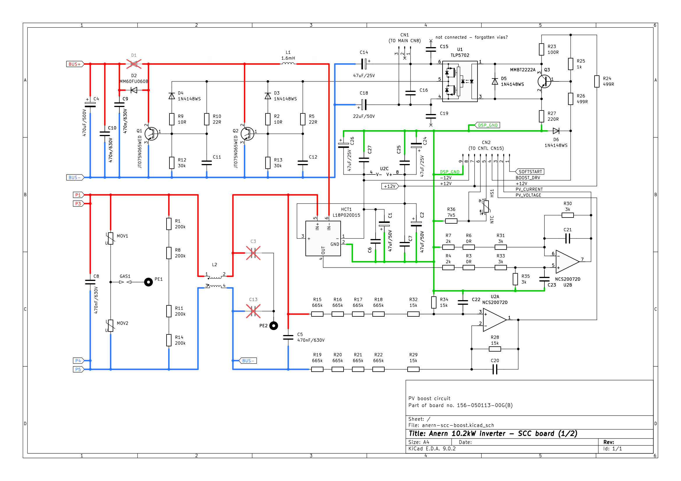
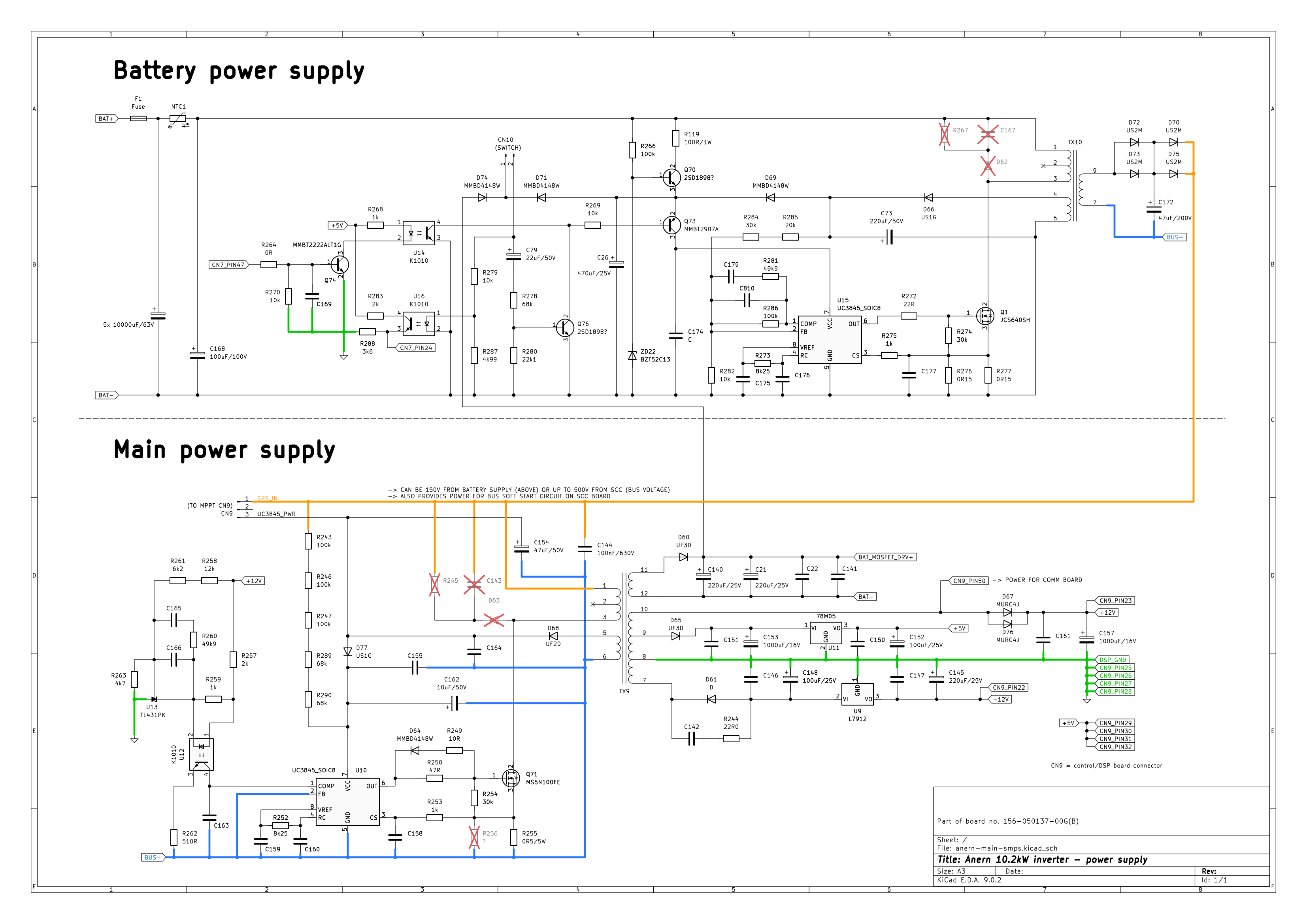
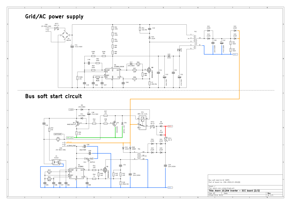
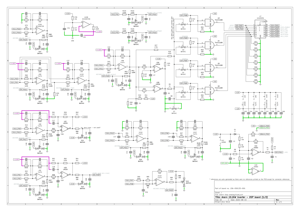
Here are some schematics that I reverse engineered from Anern Victor Max 10.2kW inverter. Should be very similar to Axpert VM models. Of course, part references and connector pinouts are different. Also ADC and GPIO assignments do not match genuine Voltronic's. The SCC board schematic is complete - PV boost circuit, voltage and current measurement, AC power supply and bus soft start circuit. Then there's a schematic of the two power supplies on the main board - this inverter uses an auxillary 150V power supply to start from the battery. Also a I attempted to trace the analog part of the control/DSP board. This was little bit harder as there were no printed part references on the board. But all op-amps are there, nothing important (for understanding the circuit function) should be missing. [15/Aug/2025 added the remaining "digital" part] I think there will be some errors, so every feedback is appreciated. I can provide KiCad project files if anyone is interested.



-
I couldn't find any 20A derating in the firmware. Did you also check program 11 (maximum utility charging current)? Which firmware version are you running?
-
Are you sure there's some "easy" way to do it? I mean, the flash registers are protected by CSM password too. I was not able to erase the flash using Uniflash when the CSM password was programmed. @Axlotl You can replace the chip with a new one, modify the firmware file to work without a bootloader and upload it using JTAG. The problem is that there may be no suitable firmware for this model available online. Which firmware version did you try to upload? Did the process finish correctly?
-
Yes, they sould be something like SN74LVC1G08. I think this pinout looks very similar, but there may be differences between various models: https://forums.aeva.asn.au/viewtopic.php?p=94872#p94872 That's possible but probably not worth the effort, if you have a replacement board coming in 14 days. You would need TI's debug probe, like XDS100. And the first steps with CCS are really not easy. The current version doesn't even have an option to create an empty project, you either have to create it from the command line, or modify some of the examples. Lots of things don't work as expected. Also you need to modify the linker file to only use parts of RAM which are not secured (these DSPs are locked with a password which we don't have).
-
Now I realized that error 53 is rather "inverter soft start failed" than "bus soft start failed". So the bus soft start is probably working correctly, otherwise it would not even attempt to start the inverter. The inverter's gate drivers are getting signal from four SOT-25 chips on the bottom side of the board ("AND" gates, IIRC). These are among the parts that may be causing this error.
-
A good way to start may be powering the inverter through the battery terminals and watching the bus voltage (red and black wire from the SCC board). When the soft-start circuit gets enabled, it should raise to somewhere around 400V within a few seconds. If this does not happen, then the corresponding output driver (ULN2003) may be faulty. Otherwise, it can be an issue with the ADC inputs, op-amps, possibly multiplexer (if this model has one).
-
Great news ! Looking at the status output, your Vmpp on PV2 seems to be only 10V above the original derate limit. That should be safe.
-
I think it's the inverter_temperature and transformer_temperature which I called "inside" temperature in my previous post, because it's a sensor on the board, in some products not even close to any transformer. inverter_heat_sink_temperatureonly takes the higher of the two values inverter_temperature and battery_temperature. scc_pwm_temperature will limit PV current if it exceeds 80 deg.
-
I'm glad it finally worked out. Warning 32 means no communitaction between display and DSP, it was probably stuck in the bootloader because of communication error. Looking forward to long-term test results 🤞
-
You would have to take the DSP board out and scrape the sticker off the chip. But there's no point, firmware version 78.08 can only run on TMS320F28066. And the reflash tool uses a specific command to enter the bootloader, which will also work only with this chip. You can see "FLASHCMD" defined in InvConfigFile.ini. I don't think so, this seems to be Voltronic's custom tool with no other alternative.
-
I'm not sure what that means. But quickly looking into the 38.17 display firmware I could only find "BDR96" and ":28062" (possibly also some other) reflash commands there, not "C28066" which your DSP firmware uses. So unless I missed something, then the USB OTG method can't work in this case. Oh, of course you're right. I forgot about the other string which is not shown there. The derating applies as soon as any of the strings exceeds 360V.
-
That probably means that the USB OTG upgrade method is not supported in this combination of display/DSP firmware. You would have to choose from the other two ones. RS232 should work in every case. And since there's a USB option in the reflash software, a USB cable should work too. But, looking at the inverter status, your PV voltage is below 350V which means that the derating condition does not seem to be the reason for the charging current to be limited to 100A right now. In such case the patch won't help you. I know you already mentioned that you have parameter 02 (charging current) set to 150A. Then it does not make much sense to me. I'll have to look exactly where the battery_charging_current status value is being taken from.
-
Neither I have a MAX model to test it. But the .inv file is actually IntelHex, so the .hex extension makes sense. The other files are generated by Arena Reflash Tool automatically. It's the same data in another format. So, Robert1968, I think your steps are correct.
-
So thanks to Coulomb, I got the exact 78.08 firmware and changed the derating threshold from 360V to 450V, patched file attached. Robert1968, you can test it, if you wish. Good luck! Note for others who haven't read the topic: We don't know why this kind of derating is there and whether it is necessary. Using this firmware may lead to a catastrophic failure of the inverter. Use at your own risk! MAXE11K_TWIN_DSP_78.08_derate_at_450V.zip
-
Unfortunately there is no easy way to do that. Manufacturers lock the chips by storing a 128-bit password at a specified address in the flash. There are multiple EASun firmwares available directly on Voltronic's server, but not the one for your inverter with the F28066 DSP.
-
I don't have the 78.08 original file, I could only find 78.07 for Axpert Max E 11 kW Twin '28066. I can patch that one. Is there any experience on using Axpert's firmware in EASun? Not sure if they are the same.
-
It is possible to modify the software, the problem is that we don't know why the manufacturer put this derating condition there. In theory I can't see which part of the hardware could be the reason for this kind of limitation. But there may be parasitic effects which only become apparent when the inverter is operated above these conditions. I mean, the risk of a catastrophic failure is very high with such software modifications.
-
Hi all, I looked at the code and I can confirm that the de-rating conditions are there and that they are only two-state - on/off, The only little difference from the chart that robert1968 posted on AEVA forum is in temperature derating. It only activates when inside temperature exceeds 45 and heatsink temperature exceeds 65 at the same time. It deactivates when both inside temperature drops below 40 and heatsink temperature below 55. One solution may be splitting the strings to get around 300-350V and connecting the rest of the panels to another inverter that would serve only as a charger, connected in parallel to the same battery.