HowardB
Members
-
Joined
-
Last visited
Everything posted by HowardB
-
Thanks, yes, that's what their manual says - seems strange, but nothing works, not on, not off, not turning on/off or off/on, leaving on, leaving off, etc, etc... Have tried numerous other things the past week. Eurolux HQ sent me a troubleshooting list for these particular globes and one of the suggestions was to bridge the contacts and see if it lights up - they say it should (once charged for 20-24hrs, which they have been), but nothing happens - this is on all 8 bulbs, which is just strange...I can understand maybe one not working, but 8 - seems almost impossible. Their other suggested possible fixes also don't work, so I've given up now - wasted 24 hours charging these bulbs plus numerous combinations and orientations in various different fittings through the house the past week - going to return them and grab some PioLED's as they are literally plug and work
-
Hi all, I have an issue with some rechargeable downlighters I bought for our two bathrooms - wanted to have some basic light when the bathrooms are used, so the seemingly easiest option was to get some of these GU10's with a rechargeable built-in battery, to give approx. 2hrs of light (although 2hrs is not really needed). I bought 8 of these Eurolux GU10's - 4 for each bathroom, as they were the only short stem ones I could find that would it flush in our downlight fittings: https://www.eurolux.co.za/products/G1108WW The instructions state that if the power fails, switch the switch on & off to activate the light - this does absolutely nothing, no matter what speed combination you try. When there is no loadshedding and the power is on, they work fine like normal globes... Tried using 1 single globe, as well as all 4 globes being the same on the same circuit - during a loadshedding, nothing worked - also turned them around in the holders so the pins matched, in case there was a specific pos/neg pin setting to get them working - no luck. The manual also says that the built-in battery is only charged when the light is turned on, so I tried leaving the globes switched on for the recommended 10-12 hours charge time (did 12 hours), in case the battery was not charged - still no luck. I'm now at my wits-end with these - is there something I've maybe overlooked? If not, I'll return them and maybe change the light fittings to ones that accommodate the PioLED range, as these do work as advertised.
-
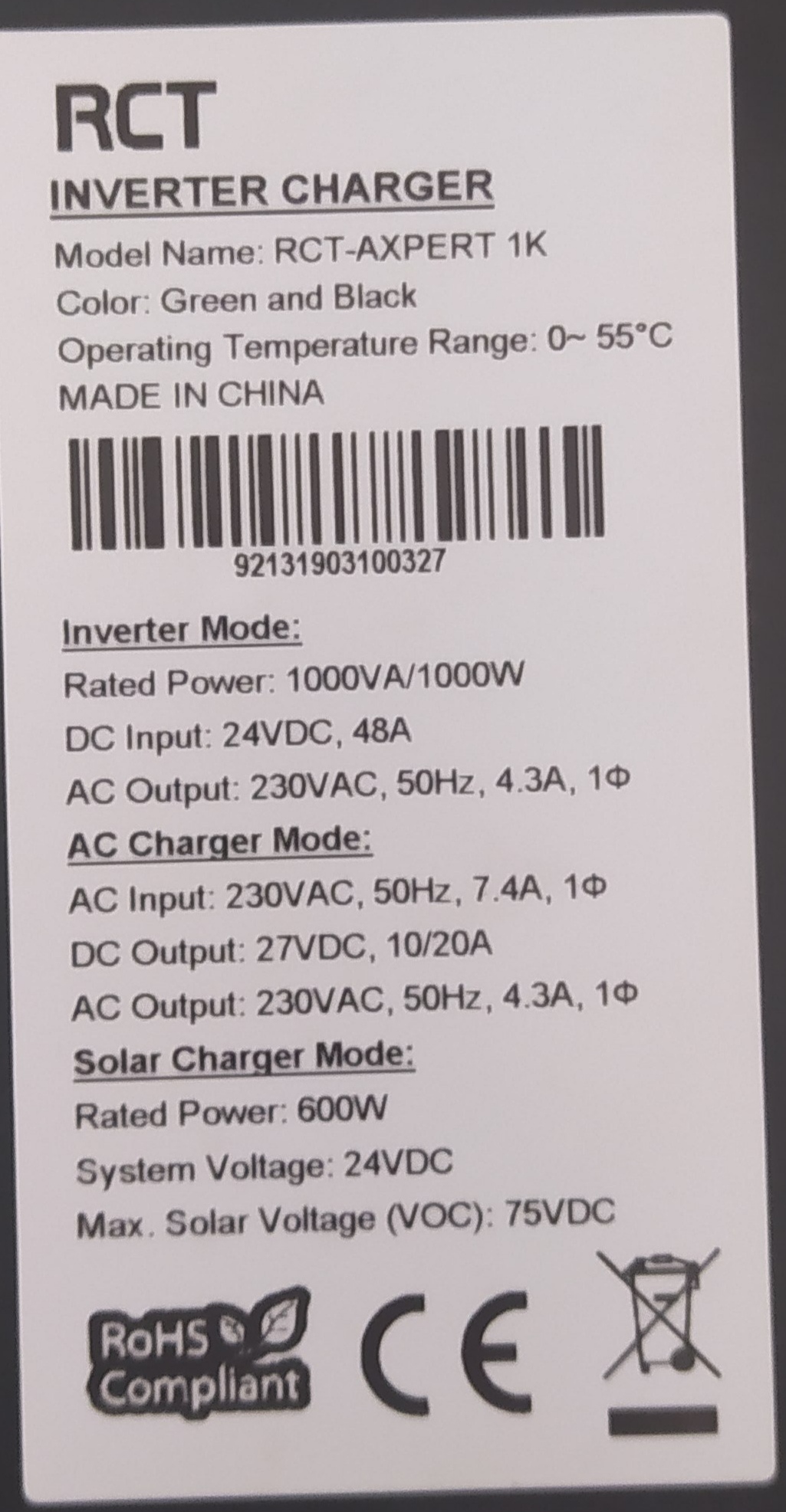
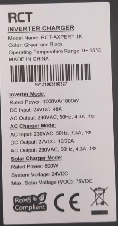
Hi all, linking on from my other post, I now want to try and have the inverter looked at and possibly repaired - are there any reputable repairers in the Randburg/Cresta area anyone knows of, or any referrals? Got a few names from a google search, but they all seem to be in the dodgiest part of Randburg in spaza-type shops; couldn't find them at all when I drove to their given address - not willing to try my luck with them, even though they seem to have decent customer ratings... Model specs are:

-
Great, thanks - I have a few spare voltmeters and will add them to monitor the difference.
-
Many thanks! The voltages did seem a bit on the high side, even though Hubble said they were the recommended, weird. Will report back once the inverter is sorted and will try those lower settings 😉
-
Hi all, Bit of a strange thing happened the other week with my March 2019 RCT Axpert 1K 24v and Hubble S-120's; only getting around to looking at the problem now - not sure if it's just bad luck, murphy's, or if there is something wrong with Hubble's charge settings, or Axpert compatibility. I had the Axpert 1K initially connected to 2x OPR120-12 OmniPower 12V 120Ah AGM batteries, in series, to give the 24v configuration (no solar involved) - all worked well with the inverter settings set to 20A charge, 13.7v float charge and 14.4v cycle charge per the battery spec given to me. The OP's were 3-odd years old and not really holding their charge any more, so I dove in and replaced them with 2x Hubble lithium S-120's. The relevant Axpert inverter settings were updated to the given Hubble charge specs, being 20A charge, 12.8v nominal, 14v float charge, 14.4v cycle charge and 11.2v cut-off per 12v battery - Hubble confirmed (as did their leaflet/manual) that for a 2-battery 24v series setup, I simply double the "v" figures, which made sense. So the inverter settings were 20A charge, 25.6v nominal, 28v float and 28.8v cycle charge. The first few bouts of 2hr loadshedding were fine and all seemed to work well, although the inverter seemed to be charging for much longer on the Hubble's and never hit the 28v/28.8v mark at all on float/bulk charges. On the next loadshedding, about 30 mins in, there was suddenly a strong electrical burning smell coming from the inverter; no fuse pop, smoke or anything - switched it off, pulled the Keto battery disconnect and unplugged everything. The inverter was not at all hot, neither were the batteries or cables. Batteries looked and smelled fine, still had 13.0v charge each. The inverter is apparently knackered, but not sure from what? No dust, dirt or miggies in the case, nothing looks popped or burnt on any of the wires or boards. Could the Hubble's themselves or their charge settings have caused this? If so, why? Are the charge figures too high for a 12.8v nominal? Who knows, maybe the inverter just blew for no specific reason - just trying to understand the problem to avoid it again - going to try have the inverter looked at and repaired, else will have to replace it - just don't want a similar issue with a new inverter blowing due to the Hubble settings Here's the Axpert sticker specs:
-
Thanks @Youda. Will try that. Just to be clear, I only need to disconnect the RJ45 cable between battery 2 and 3 - no change to the DC cables going from the 4x batteries to the inverter; they are all connected in parallel per the manual. I'll also try swapping the current master battery to one of the others and see if the same error happens. In fact, as there is no load at the moment, I might connect each battery as a single for a few days and see if any other generates a similar error.
-
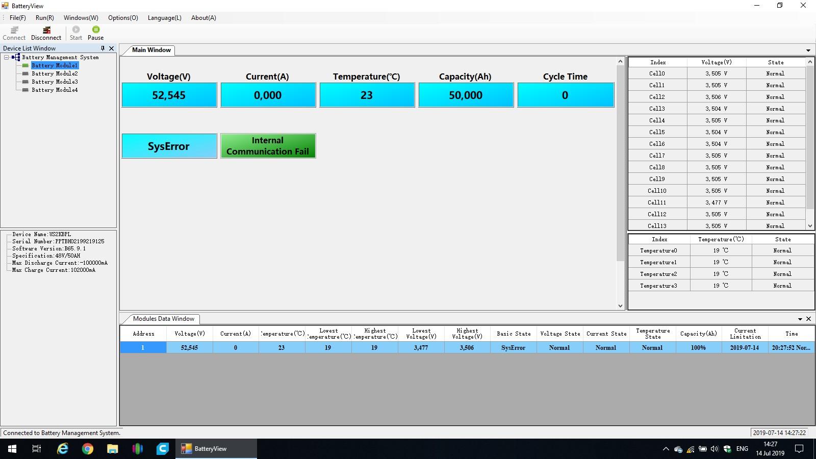
Hi all, I finally received the correct BD9 adapter and made the suggested cable for the Battery View program (thanks @Youda) - I can connect to the master US2000B, however the monitoring times out after 30s to 60s - does not seem any way to let this run without the timeout happening... Anyway, had the red alarm light again this afternoon after a few more days, so opened Battery View, connected and the only thing I can seem to see on the main monitoring page is a SysError, with "Internal Communication Fail" on the master battery, causing the red alarm. There has been no load on the batteries the past few weeks, only float charging. I cannot seem to find any reason for this or what it means. The other 3 batteries in the bank cannot be monitored with the red alarm. When the master battery is restarted, everything goes back to normal and I can see all 4 batteries and their status/details - all of which look fine and within the required ranges. Any ideas what to look at next? Any way to get this BV program not to time out so I can monitor until the next alarm to see what may be causing the alarm?

-
@Youda Thanks will try that - where do I find BatteryViewer.exe? Checked all the discs that came with the hardware, but nothing like that included. Can't find anything on the forum either.
-
All was going well since 20 April with the float charge set to 52.4V, however, got another battery disconnect alarm yesterday morning... any ideas what could be causing this? The load is only 200w or so average (on utility power), and the inverter is effectively a UPS at this stage until I can get the solar panels ordered and installed. The battery SOC shows 99.75% per BMS/ICC, with the highest cell voltage at 3.5v and the lowest cell at 3.47v - average is 3.49 according to ICC, so well within the Pylon's range.
-
Thanks @georgelza will take a look on the weekend
-
Makes sense @georgelza. I think I'm going to have to re-think the placement, or dismantle wall and floor units to accommodate the longer horizontal flushmount box. Otherwise may have to go with 2 or 3 separate flushmount units and try and make them fit.
-
Thanks guys, interesting. From a space limitation perspective, I'd prefer to mount the box so the breakers are vertical, but I'll also ask if it could be deemed compliant if the front of the DB/breakers are marked clearly with ON/OFF or IN/LOAD. After reading various articles, most of which don't relate to SA, there seems to be no real technical reason as to why it can't be done, however from a consistency and safety sake it does make sense.
-
Thanks @plonkster, just really interested to know - seems common sense is not so common any more - if a breaker shows ON/OFF, which most seem to reflect, imo this would negate the UP-is-on position problem; light switches for example are often not clearly marked (or marked at all) and can be orientated any which way you want, but it seems the DB switches must be in a certain way - all my light switches are down for on and up for off, which kind-of goes against any code that seems applicable in the home electrical circuit requirements. I'm having a tough time trying to understand some of the local codes and have honestly given up on some things as they just don't make any logical sense to me at all Will chat to the sparky about ti when I see him in a few weeks.
-
Hi all, I'm busy finalising my proposed main DB revamp and wiring layouts, but have a question I cannot seem to find an answer to: SA Home Distribution Boards generally seem to have the breaker switches running horizontally next to each other in the panel cutouts - is there any reason why they are like this and is it permissible to mount them vertically instead? Reason for asking is that my current DB is too small and crowded and I want to have an electrician re-wire and re-position certain circuits within the box, as well as add the separate inverter circuits where needed - to do that, I need a much larger DB box, possibly with 2 or 3 panels of breaker cutouts. Given the current DB is recessed and I don't want to break the wall/plaster, my only option is to look at a surface mount DB, however there is not enough room (top and bottom) for the larger surface mount box to be placed directly over the current box, hence I was thinking of mounting it "sideways" over the current box - this means that the 2 or 3 breaker panel cutouts would be vertical. Is this a problem and if so, why?
-
Quick update: When set to 53.2V for bulk charging and 52.2V for float charge, the Pylon's SOC shows 99.50% and never gets to 100%. If the float charge is increased to 52.3V it gets to 99.75% SOC and on 52.4V it gets to 100% SOC at 3.5V per cell. So I've set it to 52.4V on Thursday and so far no alarm - will watch over the next week or so to see if it happens again.
-
Thanks, have changed to 53.2V for bulk charging and 52.2 for float charge - will see how it goes
-
I was just having the same issue with my bank of 4 Pylons and an Axpert MKS5 - every few days, the master Pylon alarms red and disconnects the batteries. No loads used from the battery side, so no discharging, only float charging. Back to normal after a switch off/on of the master battery. Couldn't see anything triggering this in ICC graphs/logs. My two charging states were on 53.2V for each, but see @Youda has answered the question I was going to ask - will try setting the CC + CV to 53.2V/52.2V and see if it stops the alarm/disconnect ever few days.
-
+1 for Segen Solar in Strydom Park - I think stock arrived a few days ago - collected two more US2000's from them yesterday afternoon. I use Bonanza Tech - Alberto is very helpful, comms are good and his prices are fair - no shipping for me as I live close to Segen, just collect when ready.
-
Thanks @Sidewinder will try that.
-
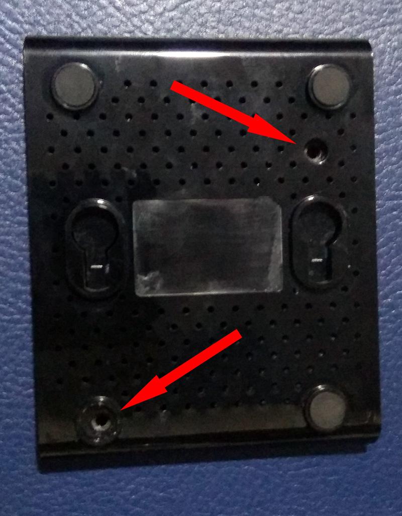
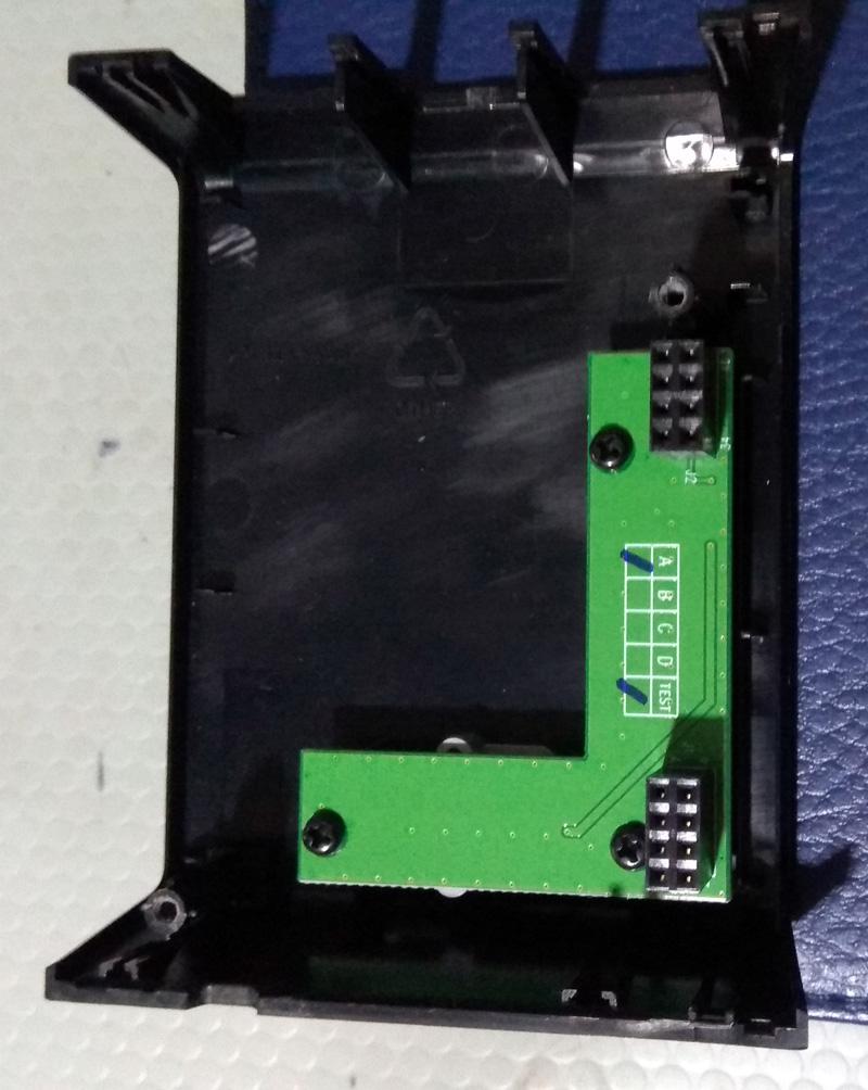
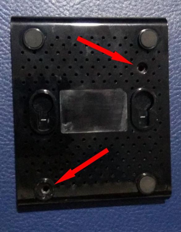
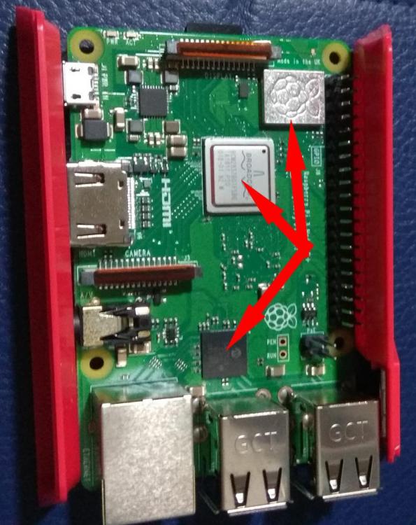
Thanks for the heads up. I opened my ICC RPi and see it doesn't seem to have any cooling fins on the components - I'm not even sure where they are supposed to go - will see if I can find some (may have some old smallish PC VGA card fins lying around) and see if they bring the temps down at all without the fan - otherwise I may design and/or download a 3D file for printing, one with a fan in the top. I'm looking at setting up OctoPrint at some point, so may look at some dual cases/stackers with cooling options. Have seen a few cases at PiShop, but don't really like the look of them... picky I know To open the ICC RPi case: There are two screws - one visible and one under the rubber foot (the foot diagonally opposite to the visible screw) The case should split open fairly easily. The Pi board is connected to the header attached to the top of the case (where the power button is) - pry off carefully...the header is screwed to the top of the case. Now, I know nothing about the PI (or very little at this stage), so I have marked where I think the heatsinks must go - if someone can confirm for me and I'll give it a bash with the ones I can find. TBH, I'm not sure about that top-right marked part - what is that? I assume the processor is the lower marked part and the middle part seems to be the wifi/LAN chip.

-
Thanks Riaan. Will take a look and see what I can find
-
Thanks @Riaanh Here's the case: I'm one of those neurotics that have to have PC's, steppers, etc running as cool as possible! I haven't managed to figure out how the case is opened yet, but will read up a bit about it and see what I can find.

-
Thanks @Sidewinder I wasn't aware there were cooling fins to be installed - the unit was supplied bundled with their ICC software loaded and I just plugged in and connected. I haven't opened the Pi case (which looks very different to others I've seen - maybe their own proprietary version?) but will try and open up and take a look. Who would supply the cooling fins, someone like PiShop?
-
I don't see why it can't. I understand that each battery must be earthed to the cabinet or to a common earth terminal. If it all goes to the DB lug, then should be fine. Mine runs from each battery to the battery cabinet common earth then to the DB earth.