Supergeek
Members
-
Joined
-
Last visited
Everything posted by Supergeek
-
Hello everyone, Looking for some input from the electricians on the forum, mostly to make sure that the aircon installer does not take shortcuts and what not. I am looking to install 4 split unit aircons (all 12000BTU), placing the outside units in a single open location on a wall outside. What are the rules (SANS) for wiring theseinto the main DB? I understand that these are all supposed to have dedicated breakers of 25-ish A in the main db, with a isolator for each unit fairly close (1m?) from the outdoor unit. Outside isolator to be 2P swithcing both neutral and live. BUT, instead of running 4x cables and having 4x breakers in my main db, can I instead run a single 10-16mm cable to a sub db that I will install somewhere inbetween those 4 units, off say a 60A breaker from the main db? In this sub db, I will then have 4 DP breakers, one for each of the units? Can this then also be considered an isolator per unit? Or must there be a seperate isolator between the breakers and the units? Asking mostly to understand what would be considered good practice and pass inspection. Thank you!
-
Hello @NeilFer, Yes, I have CANBus comms to my stack of Pylontech US3000C's. I have not attempted a firmware upgrade just yet, but it is definitely something I will be looking into in the next week or so (probably the weekend). What firmware version are you running?
-
Hello @NeilFer, Only had my Lux SNA's on for a day and a bit and still scratching my head about some of the settings, but from what I have read in your post this sounds like an obvious bug in the Lux firmware. It does not make sense that there would be no charge after a successful AC charge, and then suddenly the charge happens when you power cycle the Inverter. I would suggest you engage with Lux support, and be ready with some video evidence of your issue (I am saying this because the language barrier is broken down somewhat with a visual example of your issue). Good luck and kudo's on your BMS board!
-
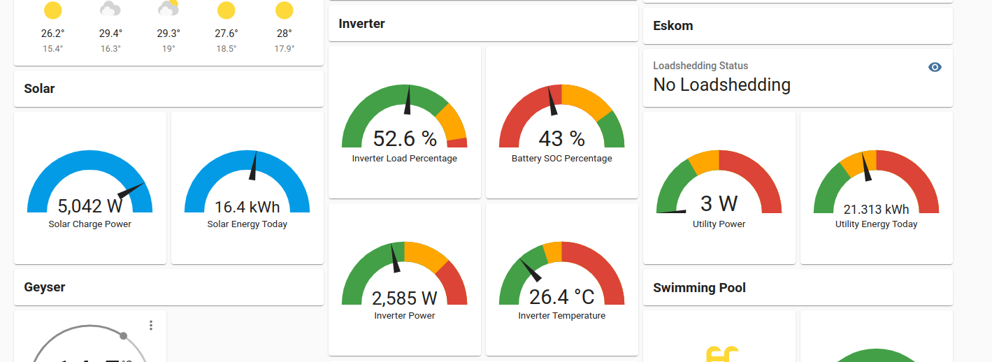
Hello @JO+eand @Rid00. I have literally just completed my conversion from a Growatt SPF5000ES to 2 x Lux SNA5000's. I am successfully pulling stats from the inverters into Home Assistant / Grafana using lxp-bridge and a little bit of Node-Red-fu. What I am curious about is how you guys are using the stats, what you have done, what you have graphed out and visually presenting and how you guys are using these stats for automation (if at all). Bonus points for pictures. I am planning on doing a quick little guide on how to achieve what I have done and posting it on the forums here somewhere for other people to use. Would be nice to have some additional insights / ideas. Thank you!
-
This bit me earlier this afternoon. I assumed it would be straight through. Thank you, this helped.
-
Link is no longer valid. Could you kindly put the files you have on a Google Drive link for the rest of the Growatt folk here? It is kinda hard to get these out of Growatt support without a massive back-and-forth (my experience at least). Thank you!
-
Depending on the size of your element (2kW, 3kW, 4kW), one of these should work. This works neatly for 4kW. It is a bit overkill for < 4kW. https://www.communica.co.za/products/jqx40f-2z-ac240v?variant=30861178896457 Just tuck it nicely into an enclosure with your sonoff. OR, you could go all fancy and get a relay that has a base that you can din-mount and then slot that into a distribution box.
-
Yeah, this side pushing 62A-ish (Centurion). But remember that he will probably be pushing 60A at 16:00 this afternoon when we are at 5A.
-
The perks of living in a city that has sun until 11PM. I am down to 50ish watts. On a serious note though - In Cape Town, optimal summer conditions, until what time can you get PV production?
-
100%, happy to help. Yeah, the other side effect of not relying on the growatt servers is that you do not see a 15 minute delayed / aggregate view of the data. It is literally as realtime as how frequently you poll the ModBus endpoint. NodeRed is a little bit of a learning curve, but not crazy complicated once you get the hang of it. And to answer your question about the USB connectivity - Yes, it would be preferable to have a dedicated device like a raspberry pi, or old laptop / computer that you can physically connect to the inverter. I am not sure what your HA hardware looks like? Is it a pi? If it is, and it is close enough to your inverter and it has some spare USB ports, you can plug straight in there and use the NodeRed addon for HA even. See attached monitoring setup and example of what you can see / do in HA.


-
Hello @uncappedshady, I used to have the same issue running firmware 04x.04 and things seem to be a bit more "sane" with firmware 04x.06. I can now use the PV+UTI mode to blend those two sources to charge the battery, whereas 04x.04 simply refused to use ANY UTI while there was still some PV available. I can most certainly help you to achieve this in an automated way. Yessir. I got this working using ModBus and a USB cable plugged into the inverter. Then using NodeRed to automate this process and exposing it to HomeAssistant (In fact, all the inverter stats are displayed on HA / Grafana using this neat little local-only method). I have to note that I am not using any of the Growatt datalogging features (I actually think the datalogger blocks physical access to the USB port because of its size), and all of this is done on your local network with local devices. I can walk you through this process and hopefully with a little nudge from your side we can publish it on a thread here for use by anyone else interested. So far I have just been lacking the motivation to actually publish the guide here.
-
What is your AC2b setting on? You cannot set the one lower than the other.
-
Translation courtesy of Google Translate: Hi all! A situation has arisen, the inverter has been registered, but the credentials have been forgotten. When registering, it says that such a device is already registered. How do I delete my Watchpower account and create a new Watchpower registration? Inverter Axpert MAX 8000 Thanks everyone! Sorry for my english, english is not my native language. Peace to all!
-
Hello @broloks, Thank you for your feedback, and thank you for the github link, that was an awesome find! I managed to make my way over to https://github.com/celsworth/lxp-bridge by the same author that is more in line with what I was looking for. So, I think based on your feedback, I am comfortable with the monitoring aspects of the inverters.
-
Hello @JapieSkapie, thank you for the feedback. I have been keeping a close eye on the charge current value, it seems that with the latest firmware (04x.06) the inverter is actually getting those values from the BMS and adjusting them continuously. I noticed when the batteries had a SOC of less than 90% the charge current would be set to 100A, 90-94% the charge current would be set to 66A and 95%+ it would reduce to 44A. I have not seen this behaviour before, but it might also be because I have not paid attention to it. I have since yesterday experienced some other oddities that might or might not be related to this firmware. I had the inverter cut out (stopped supplying inverted power) when I was running off PV and Batteries and the loadshedding kicked in (AC supply was removed, and unused at the time). At this time part of the LCD screen also froze up, so definitely seems software related. Had to do a complete shutdown and cold start for this to get fixed. Will keep an eye on it and post back here in case someone else has similar experiences.
-
Hello everyone, This post is for users / installers for Luxpower SNA5000WPV inverters. I am considering swapping my current Growatt SPF5000ES for multiple Luxpower devices (I want to upgrade to make provision for my 11-ish KW peak hour consumption and Eskom have now finally made me commit). If anyone has the answer to these questions, I would appreciate it: I read in the doccies that the maximum battery discharge power is limited to 4 000W. I am assuming that this would be per inverter and that I would get a potential 8 000W / 12 000W if I parallel 2 / 3 inverters (based on available battery configuration). Is this assumption accurate? (I assume this is BMS controlled over the multiple paralleled inverters). I see also that the maximum battery charge current is 66A. Assuming that this is per inverter, based on BMS control. Assuming this amount will go up per number of inverters / batteries BMS control. Are my assumptions accurate? Monitoring - Right now I am able to use local monitoring (no internet) on my Growatt inverter using modbus and the USB port on the inverter. I have not seen any capabilities on the Luxpower that supports this (no usb port, only a RJ45 that is labelled mppt485, which I am guessing is a RS485 port but not sure what it would be used for), only that their dongle speaks to a monitoring server somewhere on the interwebs. I do not care for monitoring on the internet, but I do care a lot for local monitoring that works even when the internet is down. Does anyone know if this is possible? EDIT: Local monitoring possible, answered by @broloks, instructions over at https://github.com/celsworth/lxp-bridge Generally, how well do these inverters parallel from your experience? Any known issues / pitfalls? Thank you in advance to any users / installers that are willing to help out with the above info.
-
Hello @PeterG If you don't mind, please can you post an update here once you managed to sort out (or not sort out) your issues? Thank you!
-
Hello Everyone, This post is for those of you that have Growatt SPF5000ES inverters AND running firmware 040.06 / 041.06 AND Pylontech US3000C's (preferably multiple). I just want to confirm some battery charge current behaviour in the latest firmware - Since the upgrade from 040.04 / 041.04 -> 040.06 / 041.06, I have noticed that my maximum charge current for the Pylontechs has dropped from 100A to 44A. It almost feels like the latest firmware is not seeing my ALL my pylontech batteries). Setup: Growatt SPF5000ES Pylontech US3000C x 3 Communication using CAN. Anyone else seeing this behaviour? You can check setting 02 to confirm the charge current amperage value applied. Thanks in advance.
-
Hello Everyone, I have been looking (unsuccessfully) online for places that sell Growatt COM cards that is compatible with the SPF5000ES range of inverters. Anyone know where, has a link? Thanks in advance!
-
Hello everyone, Sane advice on this thread so far. @Deon_J - These inverters caps the amps it pulls from the panels to 18A, so if you have multiple strings that you combine, everything over 18A would be a waste and possibly result in clipping. Bottom line - Look at your panels specs (Open Circuit Voltage - VOC and Short Circuit Current - ISC specifically) and try to determine from there which combination of series panels vs parallel strings you need to combine to get the max out of your panels and into your charge controller on the inverter. Also, you could post the specs of your panels here and we can constructively debate through it to see what the best fit would be over the 2 inverters.
-
Hello @LwL, BMS comms for the SPF5000ES is pretty straight forward - it supports both CAN and RS485. No funny business like the SPFxxxxTL models. SPF5000ES using RS485 Network Cable - Cross Over - pins 1,2,3 (inverter side) crossed over to pins 8,7,6 (battery side). That is 1-8, 2-7, 3-6 Inverter Port - RS485 Battery Port - B/RS485 (this is on a Pylontech US3000C) Battery Dipswitch - 1000 (on, off, off, off). This will give you the required 9600 baud comms speed. Some US3000C's have the dipswitch installed upside down, please take note of this and just do the sensible thing. Inverter Option 5 - Li Inverter Option 36 - L02 SPF5000ES using CAN Network Cable - Straight Through - pins 1-8 (inverter side) straight through to pins 1-8 (battery side). Inverter Port - CAN Battery Port - A/CAN (this is on a Pylontech US3000C) Battery Dipswitch - 0000 (off, off, off, off). Dipswitch does not matter for CAN. Some US3000C's have the dipswitch installed upside down, please take note of this and just do the sensible thing. Inverter Option 5 - Li Inverter Option 36 - L52 This should get your comms working.
-
@PaulC - Check your inbox, I sent you a link to the firmware that fixed(for me) the issue you are describing. I could post the link here publicly, but I am not sure if there are some rules against it, or if there are some "you-shall-not-share" fineprint from Growatt that I have not seen. Also, these firmware flashes are considered a risky operation, so there is a fair chance that things can go sideways and you end up with a bricked inverter. Does anyone know about the fineprint? Also, are these public links allowed on the forum?
-
Hello everyone, Thank you for your replies. @Gerrie - Thanks for the explanation and feedback. The reason I was looking for the bond was purely to get an understanding of what is being done where, and I have read some posts that this is typically done in the main DB. Thanks for clearing that up. @isetech - Thanks for your feedback. This might be a secondary reason why I was asking. I do have an inverter, and I was wondering where this neutral - earth bonding would happen. I am trying to test my logic of what would happen in a case where you flip the main switch (which switches both L and N) and work on PV / inverter and this bond does not exist. @hoohloc- Thanks for your feedback. It was mostly curiosity to get a better understanding of how these things are done, and where. Thanks for the information about testing the voltages. This is something I have tested before, but obviously I have not tested this for all the possible variations of switches being flipped. @Carl- Thanks for the feedback and attached picture. I am guessing based on the other feedback that what you have in your TN-C-S earthing is slightly different from the TN-S earthing which I assume most new dwellings use.
-
Hello @Nexuss Thanks for the reply. Are you talking about the box that houses the 4-6 houses feeder switches outside in the street? Because I peeked in there too and I could not find the bond.
-
Hello everyone, I recently went through every DB in and around my house in search for the Neutral-to-Earth bond, not finding it. My house is in a slightly older neighbourhood, so I am curious if anyone here know where they typically did the bonding? I could not find any bond in my main DB (I expected it to be here), sub-db's (not expecting any here, so this is good), or the main disconnect switch that is outside my house, between my main DB and the utility source (I did find some very antique equipment in here that looks like it might have been an electricity meter at some point). Anyone know where they did the bonding in older houses? Some pics would be nice, if available. Thank you in advance!