


RoganDawes
Members
-
Joined
-
Last visited
Everything posted by RoganDawes
-
That would be amazing! Thank you! Aha! Makes perfect sense! I have an existing sensor with those calculations, but I had never provided it to the card. All working perfectly now. Thanks for the help!
-
Not going to comment on whether you have enough battery etc to go off grid, but can possibly help with the geyser questions. I built my own smart geyser controller, based on a geyserwise thermostat and a Sonoff THR320, all running ESPHome. I use it to dump excess solar into the geyser in the form of hot water, but can also manage them remotely, or automatically using Home Assistant. One important thing I did was to change the element from a 3kW to a 2kW, to reduce the peak draw when the geyser is running, so that the load stays under the threshold of available solar. Doing the same for your 4 geysers could take you from 12kW just in geysers to 8kW or less, depending on which are actually running. Note that this just reduces the peak load from your geysers, but they would obviously have to run longer to achieve the same amount of hot water. You can find details here: https://mybroadband.co.za/forum/threads/esphome-geyserwise-smart-thermostat.1231463/ Note that if I were to do it again, I'd try really hard to just replace the thermistor with a Dallas DS18b20 1-wire sensor at the tip of the thermostat, rather than futzing with the interposer! If you want to spend money, you could consider heat pumps as a much more efficient way of heating water (3 times). Given your goal to go offgrid, it would be smarter to reduce your consumption before investing in more batteries. Regardless of the technology you select, having some degree of load control is advisable, whether that is turning off geysers, pool pumps, chest freezers, etc. That sounds like around R12-14k each, which is about the same price as an equivalent heat pump, I think. But reducing the consumption will pay off by making panels previously dedicated to heating water available for other loads, like charging batteries. And with smart control, you can possibly change thermostats on the heat pumps to run when your batteries are near full, and there is more solar available than needed to fill the batteries.
-
Wondering if it is possible to show the water-boiler temperature next to the boiler icon, like you do for the inverter and battery temperatures? Also, seems like one of the values is not "clickable" to show history graphs, the 612W feeding the house has no graph behind it. Everything else seems to work just fine.

-
If the document says it is RW, change the definition to a RWSensor, following the pattern used by other RWSensors.
-
An alternative is to connect a regular USB-RS232 connector to the inverter in place of your Sunsynk dongle. Behaves exactly the same, except is RS232 instead of RS485.
-
Hi, hoping for some help from the Solar Assistant experts. A friend has 5 Growatt inverters as per subject line - about 3 years old. They have no dongles, and so they are not being managed properly. I'm trying to help, by setting up an ESP32-based system (or else Pi-based) to talk via RS232 or RS485 to each inverter and pull stats from them(at least), to monitor and potentially manage the inverters. One fairly large problem I have run into is the inability to change the modbus slave address on 4 out of 5 inverters, since they are all set to 1 by default. I am able to "change" the address by writing to it using modbus over RS232 via the USB-A connector, in scare quotes because the change doesn't actually take. If I change the address from 1 to 2, for example, it stops responding on 1, fails to respond on 2, but if addressed using the broadcast address (0), I get an answer from address 2! I have heard that the inverter needs to be rebooted for the change to properly "take", but we did try turning the inverter off and on again, with no success. It *was* possible to reset the address back to 1 by writing to address 0, after which it resumed responding to messages addressed to address 1. Any ideas how to make this change permanent?
-
There is no RTS/CTS required. You may well have the outbound RX and TX lines swapped. Would try that first.
-
I suspect it is something like doing a modbus write to a particular holding register (probably with the expected length of the firmware), then writing the bytes of the firmware one after another to a different holding register, then finally writing a "complete" message to either the first or a different holding register.
-
Sure, that's why you take a backup, and can reinstall it if you ever need to do an upgrade. And while doing so, log all the data written out on the serial port to see how it is done 😛
-
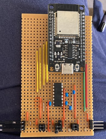
This is mine: ESP32 talks to the SP3232 transceiver (yellow wires), which has 2 channels in each direction, perfect for 2 UARTs. The jumpers at the bottom either swap RX/TX (two blocks on either side), or connect/disconnect the TX lines from the transceiver/ESP32. When the ESP32 TX lines are disconnected, the ESP32 can snoop but not transmit, which is enough for most purposes. I run ESPHome on the ESP32, because it has a ton of useful functionality (OTA updates, built in UART buffering, debug logging via WiFi, etc), and simply put the Sunsynk dongle on one side, and a DE9 cable to the inverter on the other side. The string of numbers you posted is actually just the dongle trying to identify the address of the inverter (first column). Second column (3) is a "read holding register" command, starting at address 0, and returning 9 registers. last two columns are the CRC. Apparently the inverter was not responding for some reason. Not connected, maybe? 0 3 0 0 0 9 132 29 1 3 0 0 0 9 133 204 2 3 0 0 0 9 133 255 3 3 0 0 0 9 132 46 4 3 0 0 0 9 133 153 5 3 0 0 0 9 132 72 6 3 0 0 0 9 132 123 7 3 0 0 0 9 133 170 8 3 0 0 0 9 133 85 9 3 0 0 0 9 132 132 10 3 0 0 0 9 132 183 11 3 0 0 0 9 133 102 12 3 0 0 0 9 132 209 13 3 0 0 0 9 133 0 14 3 0 0 0 9 133 51
-
It’s not easy, I’m afraid. As of last year, the tools for reversing an ESP32 RISC-V binary were not exactly user friendly. There are lots of debugging / logging statements which should help to give an idea of what the code is supposed to be doing, if you can figure out the memory base addresses, etc for your decompiler.
-
I actually built something like this, based on an ESP32. I posted some pictures of it, and a little description, here: https://infosec.exchange/deck/@RoganDawes/111595769934719217 Sorry, the pictures are too large for this forum 🙂 ESP32 has 3 UART's, I put an SP3232 on some veroboard to get 2 inbound signals and 2 outbound signals, mapped to U1RX/U1TX and U2RX/U2TX. The jumper pins in the middle let you switch from just snooping to active interception, by connecting the TX signals, and breaking the "Straight through" connections in the middle. And yes, while it is possible to pass through the data from the genuine dongle (running e-linter firmware) to the inverter, and its responses in the other direction, and then issue your own commands when it is quiet so as not to trample over the e-linter comms, actually identifying and using those intervals of quiet is not the simplest problem to solve. I think I mentioned it above, but another approach is to emulate the e-linter firmware using Wokwi, and forward the emulated UART to the dongle. Still some impedance matching required (e-linter firmware will expect a response within X ms, otherwise will resend the query, so you can simply drop a duplicated query, etc, etc).
-
Just to be clear, I used a USB-TTL (3.3V) adapter, directly connected to the header holes on the PCB, not an RS232 UART connected to the DE9.
-
Ok, so I finally took the time to flash ESPHome onto my Sunsynk wifi dongle. Took a while to figure out the details, which I wrote up in another thread: https://powerforum.co.za/topic/28044-anyone-noticed-weird-behaviour-from-their-sunsynk-inverter-charging-when-not-supposed-to-resetting-daily-totals-etc/?do=findComment&comment=202244 The end result is that you have a dongle running ESPHome, powered neatly from the inverter via the Ring Indicator pin of the DE9 connector, polling the inverter using modbus over RS232 at 9600 baud. The diff from slipx06's original ESPHome config is minimal: diff -w ESPHome-1P-Sunsynk-Deye.yaml sunsynk_dongle.yaml 12c12 < board: nodemcu-32s --- > board: airm2m_core_esp32c3 14a15 > variant: esp32c3 60,61c61,62 < tx_pin: GPIO1 < rx_pin: GPIO3 --- > tx_pin: GPIO5 > rx_pin: GPIO6 67d67 < flow_control_pin: GPIO16 Basically, change the board to an ESP32C3 (I just picked one, there may be better options), set the variant, and update the UART pins. Also, delete the modbus TX control pin, because RS232 is full duplex. Shout if you have any questions.
-
So, it wasn't as simple as I thought it would be to get ESPHome running on the Sunsynk dongle. Flashing is not too tricky, although I do end up contorting my fingers a little, holding 3 jumper wires for G,R,T and a pair of header pins with a jumper on them to bridge GPIO0 (aka "short for ISP" - edit: turns out this is GPIO8 on the C3) with one finger, and holding 3v3 against the capacitors to the left of the C3-Mini module to power it. I used: esptool.py -p /dev/cu.usbserial-01E7DF5F -b 230400 read_flash 0 $((4*1024*1024)) sunsynk2.bin to take a backup (it's a 4MB part, so you can do the calculation manually if you are using Windows). Flashing a minimal config ended up in a boot loop when powered as above via a 3v3 supply, held against the decoupling caps. I guess it wasn't enough to power the WiFi when it initialises. So, using a DE9 breakout, and feeding 12V on the RI (pin 9), and ground on pin 5, I was able to get it running stably. It took me an AGE to figure out what pins to use for the uart! I first thought I'd be clever and use the ESPHome kickstart firmware to dynamically adjust the pins, and wasted a few hours trying to get that to work, firstly making changes for the ESP32C3, and then just iterating through the pins and looking for behaviour on the RX and TX pins of the DE9 connector. All for naught, the kickstart firmware just wasn't working properly for some reason. BTW, I did test restoring the backup firmware, and it worked perfectly (when powered using 12V). It was actually the stock firmware boot loop when powered via 3v3 to the capacitors that clued me in to checking for power problems. In the end, my diff to slip06x's config on github was pretty minimal: diff -w ESPHome-1P-Sunsynk-Deye.yaml sunsynk_dongle.yaml 12c12 < board: nodemcu-32s --- > board: airm2m_core_esp32c3 14a15 > variant: esp32c3 60,61c61,62 < tx_pin: GPIO1 < rx_pin: GPIO3 --- > tx_pin: GPIO5 > rx_pin: GPIO6 67d67 < flow_control_pin: GPIO16 I did also figure out the GPIOs for the LEDs (3 and 7 for the red and green LEDs, respectively), but haven't yet bothered adding those to the config. With that, you can now flash ESPHome onto your Sunsynk dongle, and detach yourself from the cloud entirely.
-
Yes, potentially. It should be easy enough to flash it back should it be needed, just take a backup before overwriting it. (Sorry, I missed this when originally posted) No, I haven't done it yet, but cannot imagine it will be terribly difficult. You only have to do the manual flash using a USB-UART the first time, after that you should be able to do OTA (assuming you included the `ota:` configuration). I used a regular USB-TTL UART (3.3v) which showed no conficts with the RS232 transceiver, but perhaps because it is a CP2104-based adapter and has high drive strength to override pullup/pulldowns. (e.g. see https://diysolarforum.com/threads/hacking-the-new-growatt-wifi-f-modules.43231/ for some discussion about reflashing dongles for Growatt inverters) It should certainly be reversible if you take a backup of the firmware before flashing ESPHome, that you can then flash back if you need the firmware update capability.
-
Yeah, I think I'm going to look at flashing ESPHome onto the Sunsynk Dongle. That will let me eliminate the RS485 connection from the inverter, as well as stop outside interference. If anything changes, it will be because I did it, not anybody else! Will back up the e-linter firmware in case I need to update inverter firmware for any reason, but disconnecting it from outside influence is appealing to me.
-
Yeah, that could explain it. But it doesn't REALLY explain why a serverside mixup should mess with readings taken directly from the inverter! 😠 I guess if the server is pushing the time down to allow the inverter to maintain accurate time, and the server doesn't have accurate time, the inverter will simply accept it. Judging by the number of times my daily figures were reset, they tried a bunch of things over a couple of days to try and get the time zones right! Guess I need to put a read-only filter in between the dongle and the inverter to stop this sort of crap happening. Or just disconnect it entirely. (And by "read-only filter", I mean a program that is making sure that only modbus read commands are passed through). Crap that should not be required if Sunsynk was not messing around, and limited themselves to only issuing read commands.
-
Thanks for the response! I can confirm that the first/last time on my inverter is midnight. It has been working perfectly like this for about a year, with Home Assistant switching "Use Timer" on and off every time my geyser starts heating in the evenings. Something went weird over the weekend. Just trying to see if anyone else saw similar things.
-
Hi folks, I noticed on Saturday that my Sunsynk 8kva inverter was charging the battery from grid when it was not supposed to (was in the "No charge from gen or grid" program after 8am). I've also seen weird behaviour with the daily totals, which were resetting during the day, rather than at midnight. In the above image, you can see normal behavior for a Day Grid Import value, increasing until midnight, when it resets to zero again, Monday to Friday. On Saturday and Sunday, the graph is all over the place, resetting several times each day to zero. Then suddenly, it starts behaving itself again this morning. My readings are coming via RS485 using kellerza/sunsynk, which has been working perfectly for months, and yes, the Sunsynk dongle is still connected. I tried to correlate with the Sunsynk app, but was unable to find any graphs showing the Daily Grid Import. Did anyone else see anything like this?

-
Yes, the config files I linked to are for ESPHome. To be honest, I'm not 100% sure which BMS the Narada batteries are using. These ones belong to a friend of mine, I actually have Greenrich batteries that use Pace BMS. You can access those using an RS232 cable with https://github/com/tertiush/pacebms or, if you use pbmstools.exe, you can configure the RS485 port to talk modbus. It seems to talk Pace BMS protocol by default otherwise (or is disabled, I don't recall which now! 🙂 ). Not 100% sure exactly how PBMSTools.exe works, whether over RS232 or RS485, but I imagine it should work over 232, and then enable 485 at the least.
-
For what it is worth, ESPHome supports packages, which are essentially include files that can accept variables. So, if you are duplicating entities to handle a master inverter and a slave inverter, or 4 identical batteries, this is a great way to go. You can see an example of this here, where I monitor 2 Narada batteries over RS485. packages: battery_1: !include file: .narada-npfc.yaml vars: modbus_controller_id: narada_39 battery: Battery 1 battery_2: !include file: .narada-npfc.yaml vars: modbus_controller_id: narada_40 battery: Battery 2
-
Looking to do something similar, except I have 5 inverters and 4 batteries that need to be considered. At least the batteries have a daisy chain/passthrough connector, but the inverters do not. I found these (https://soundtech.co.za/rj45-ethernet-splitter-2-pack.html): Which should do the trick, I hope. Just make a short pigtail for each inverter, then daisychain ethernet cables from one to the next. Makes it less of a star topology, at any rate. Ideal would be a RJ45 version of this, although this might even work, if the necessary pins are present: That said, it might impinge on any neighbouring connectors, so having a short pigtail is probably a good approach.


-
That’s probably going to be the simplest approach. Although the utility of registering MAC addresses with your AP is debatable. In order to try access your network, the attacker will need the preshared key as a first pre-requisite. And once they have the key, they can simply snoop to find an authorized station transmitting on the network, then clone that MAC address.
-
There are any number of ways to get it. But I suspect this is an XY problem (https://en.wikipedia.org/wiki/XY_problem). Why don't you tell us what you are trying to achieve, rather than how you think you need to go about doing it? To answer the question anyway: 1. look on your router for assigned clients and their MAC addresses. 2. ping the IP address, then check the ARP table for the corresponding MAC. 3. ping the IP address while running tcpdump -ne 4. Open the dongle and use a USB-TTL adapter with esptool to query the ESP32 directly. etc


