RoganDawes
Members
-
Joined
-
Last visited
-
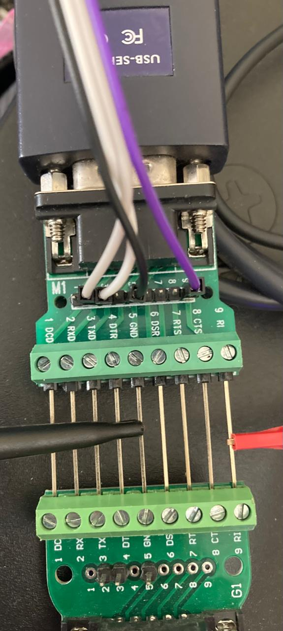
I revisited this for a friend, and found it easier and better to provide 12V to the dongle through the DB9 connector (12V goes to RI - pin 9) while holding a bridged 2-pin header in the "ISP" holes to activate the programming mode. Once this is done, you can remove the header, and add 3v3 UART to the uart pins, and flash as needed. I also uploaded my config files to github: https://github.com/rogandawes/esphome-configs/
-
Glad you came right!
-
-
Hey @WannabeSolarSparky Were you successful flashing the dongle? Or do you need help? FWIW, the capacitors to the left of the ESP32 should be identified with the ESP32 in vertical orientation, antenna at the top. (Even though that ended up not being enough to actually run the dongle that way, it is still enough to program it at least!)
-
-
-
If you are still struggling with this, I would strongly suggest putting some monitoring on the battery, and ideally the inverter as well. It doesn't have to be expensive or complicated. The Greenrich battery can be monitored with the Pace BMS software, using an RS232 to RJ9 cable. The Sunsynk inverter can also be monitored with an RS232 DE9 cable, which is connected to the dongle port (since you are not using the Sunsynk dongle), and monitored using any modbus software. I use HomeAssistant to store/aggregate/present the statistics, and KellerZA/Sunsynk integration to collect data from the Sunsynk, and TertiusH/PaceBMS to collect data from the Greenrich.
-
If anyone still cares about the Shine-Wifi-F dongles, and would like to use them for complete local control of their inverters using Home Assistant, I wrote up how to reprogram them with ESPHome here: https://powerforum.co.za/topic/32073-growatt-shinewifi-f-reflashed-with-esphome/
-
Turns out I was somehow using an older version of ESPHome, which contributed to the Out of Memory problems I was having. Try make sure you have an up-to-date installation. I recovered about 10-14kB doing so! 20%!!
-
-
Here is the YAML that I came up with. Note that the ESP07S is quite RAM limited, and I ran into "Out of Memory" conditions when enabling too many features. Main symptom of this was failure to connect to WiFi, or failure to complete OTA updates (leaving the esphome program on the client hanging)! esphome: name: growatt friendly_name: Growatt esp8266: board: esp07s # Disable logging logger: # level: VERY_VERBOSE # level: INFO # the below lines move logging to the alternate UART pins # this exposes the TX line on the GD25Q SPI flash CS pin #1 # which can be snooped with a chip clip or pin grabbers. GND is pin #4 # If you want to keep the hardware UART for the modbus uart, # uncomment the baud_rate, and comment the hardware_uart # This is advised for "production" deployment! # baud_rate: 0 hardware_uart: UART0_SWAP # Make sure that the logger level is at least DEBUG # This is good for monitoring free heap space, etc # .debug.yaml simply contains the example configuration from # https://esphome.io/components/debug.html # <<: !include .debug.yaml # Disabled by default, because of limited RAM # required for the pcf8563 #i2c: # scl: GPIO4 # sda: GPIO5 time: - platform: sntp id: sntp_time # on_time_sync: # then: # pcf8563.write_time: # - platform: pcf8563 # id: pcf8563_time # address: 0x51 # SPI bus is connected to the GD25Qxxxx SPI NOR Flash chip # Mine was covered with conformal coating, so I couldn't make out the # exact part number # e.g. https://eu.mouser.com/datasheet/2/870/gd25q64e_rev1_4_20210820-1825464.pdf #spi: # clk_pin: GPIO14 # mosi_pin: GPIO13 # miso_pin: GPIO12 # There's no support for flash chips in ESPHome at the moment # But the CS pin is GPIO15 # Enable Home Assistant API api: ota: platform: esphome wifi: ssid: !secret wifi_ssid password: !secret wifi_password # Enable fallback hotspot (captive portal) in case wifi connection fails ap: ssid: "Growatt Fallback Hotspot" captive_portal: #web_server: light: - platform: status_led id: status_led_ output: led_red internal: true output: # Green LED - id: led_green platform: gpio pin: GPIO0 # Red LED - id: led_red platform: gpio pin: GPIO2 # Blue LED - id: led_blue platform: gpio pin: GPIO16 uart: - id: modbus_uart_master baud_rate: 9600 rx_pin: GPIO3 tx_pin: GPIO1 # debug: # direction: BOTH button: - platform: safe_mode name: "Safe mode" binary_sensor: # The button is connected to the ADC - platform: analog_threshold name: Button sensor_id: adc_button threshold: 0.5 filters: invert: sensor: - platform: uptime name: Uptime Sensor entity_category: diagnostic - platform: wifi_signal name: "WiFi Signal Sensor" update_interval: 60s entity_category: diagnostic - platform: adc pin: GPIO17 id: adc_button update_interval: 1s filters: delta: 0.1 # Use the stream_server for remote modbus RTU access #external_components: # - source: github://oxan/esphome-stream-server #stream_server: # - uart_id: modbus_uart_master # port: 502 modbus: - id: modbus_master uart_id: modbus_uart_master modbus_controller: - id: growatt_master address: 0x1 modbus_id: modbus_master setup_priority: -10 # .growatt.yaml contains the modbus register definitions packages: master_inverter: !include file: .growatt.yaml vars: modbus_device: 1 modbus_controller_id: growatt_master inverter: Master
-
-
Hi folks, I was given a ShineWifi-F dongle by @Demo after his Growatt inverter was water damaged. There are a few threads about reprogramming the Shine-Wifi-F dongles (e.g. https://diysolarforum.com/threads/hacking-the-new-growatt-wifi-f-modules.43231/), but one of the constant problems is programming it, because of the RS-232 transceiver connected to the ESP07 modules RX and TX pins. Some folks desoldered the transceiver, others cut traces, etc. Some had success with particular USB-TTL adapters, but the CP2102 that was said to work there didn't work for me. Others had problems providing enough power. I approached it somewhat differently, starting with a USB-RS232 dongle, and a RS232 breakout board. I cut a USB extension cable in half, and connected the white wire to the TX pin (pin 2) of the breakout, and the green wire to the RX pin (pin 3). Black obviously went to pin 5 (Ground), and red went to pin 9 (Ring Indicator). In fact, the red wire doesn't need to be connected to the breakout at all, but it simplified things physically. I also had a 12V supply, which I connected to pin 9 and pin 5, to provide power to the dongle. I also put a jumper between Ground and GPIO0 on the dongle to put it into programming mode when power was applied. With that done, I could simply run esptool.py to pull the original firmware off as a backup, and then install my own ESPHome firmware on it. Thanks again to @Demo for the dongle.

-
Probably better to not flash your dongle, I agree! There are two ways to connect to your inverter: RS485 and RS232. I'm tempted to say that RS232 is simpler than RS485, as I have seen a bunch of people struggling with the RS485 dongles specific requirements. Some dongles work better than others, some need a resistor to be added or removed, etc. There is a lot of documentation on the kellerza wiki on that approach, and I won't repeat it here. There is less on the wiki about RS232, which is how the sunsynk dongle itself connects to the inverter. If you decide that you don't need the sunsynk app on your phone for remote access to data and control, you can simply connect your Home Assistant box using a USB-RS232 adapter, and a DB9 serial cable. Unscrew the dongle, plug in your DB9 cable, and connect it to the USB-RS232 adapter plugged into the Home Assistant box. Install the kellerza/sunsynk addon according to the instructions on the wiki, configure it using the appropriate single phase/3 phase sensors for your inverter, and you should be good to go. It can be a bit more complicated if your inverter and your Home Assistant server are too far from each other to connect directly with a cable. In that case, you have two options. RS485 is designed for longer runs than RS232, so it might end up being necessary to go that route. Alternatively, you can use mbusd (Modbus Daemon aka server) on a raspberry pi or other small linux computer (even a Pi Zero is enough), to make either the RS232 or RS485 port accessible via wifi. i.e. instead of a long cable, you substitute with a computer conveniently located close to the inverter, and use wifi instead. Let me know if you need to go down this route.
-
Latency can easily be sub 10-second, although you can control the polling frequency for the parameters that are super-important. I actually have two different systems polling my inverter, because I'm a bit ridiculous :-) I originally set up the KellerZA RS485 integration, and then subsequently figured out how to reprogram the Sunsynk dongle as well. That is now running ESPHome, and I'm happy to share that procedure and config if you want it. I'm happy not to have the Sunsynk dongle talking to the cloud, since their clock sync foulups resulted in my inverter discharging at the wrong times. Although I do recognise that it may be useful to have vendor firmware available in case I ever need a firmware update. I took a backup so I can restore that if necessary. However, the kellerza integration is actually still the primary source of data for me. And yes, all the figures that you see in their diagram on the inverter itself are available, and more. You can get an idea of what is available here: https://github.com/kellerza/sunsynk/blob/main/src/sunsynk/definitions/single_phase.py Those that have RW in their class are read-write, i.e. can be changed.
-
The other thing you can do is set your geyser temperature a bit higher, if you have excess sun. That turns it into an additional "battery" - it stores energy as hot water, and when the water is hotter, you need less of it to have a comfortable shower, so it lasts longer. I made a smart controller for my geyser using a geyserwise thermostat, and a Sonoff THR320 smart relay. It's rated at 20A, so should be ok for your 15A/3kW element. I actually installed a 2kW element so it would have less of an impact on my inverter (also 8kW, like yours). The big thing is that I can automatically (via Home Assistant) monitor the inverter and the battery levels and rate of charge, and adjust the thermostat from 45C normally up to 70C when the batteries are 70% charged, and charging at more than 2.5kW for 5 minutes, and back to 45C when the batteries start discharging at more than 500W for 5 minutes. Total cost around R650, and my 150l geyser soaks up 4kWh of solar taking the water from 45C to 70C (13C/hour at 2kW, takes 2 hours). Obviously, tweak the levels, rates and temperatures according to what works for you. Depending on how technical you are, and your appetite for complexity, you can also put ESPHome onto the Deye/Sunsynk dongle, or make a new one based on an ESP32 microcontroller and a RS232 transceiver. Then ESPHome on the dongle can talk directly to ESPHome on the Sonoff THR320, and you can skip Home Assistant entirely. Or, an ESP32 with a RS485 transceiver can do the same thing.
-
-
I made my own smart geyser controller with a Geyserwise thermostat (R260) and a Sonoff THR320 (20A relay, R400), having first replaced the element with a 2kW. Has been working perfectly for 2-3 years now. Sonoff is running custom ESPHome firmware, and switches between a target of 45C and 70C based on available solar power/grid availability, etc. I calculate I can sink about 4kWh into the water tank (2kWh ~= 13C difference in a 150l tank)
-
I made a custom geyser controller based on the Geyserwise thermostat (which you can get for about R260), and a Sonoff THR320 (about R400). I also changed the element in my geyser to a 2kW from the 3kW it had orignally. I was actually fortunate enough to have my geyser pack up, and get replaced by insurance at the time, so I got the installers to fit the new element before it was even installed in the roof. I have an 8kW Sunsynk, and 10kWh battery. Geyser is on the AUX section of the Sunsynk, though in hindsight, I'd be happy to move it to the essential loads, freeing up the AUX for a generator at some future point. I am monitoring my Sunsynk using the KellerZA/sunsynk integration in Home Assistant, and the Sonoff is flashed with ESPHome firmware, exposing the geyser as a generic thermostat (heating only). I also have some automations that monitor the state of the grid (based on Sunsynk grid power, which normally idles at 30W to prevent backfeeding, but obviously drops to zero when the grid disconnects), the state of charge of the batteries, and the rate of charge of the batteries, and apply automations to turn off the geyser whenever load shedding is active after 16:00 and before 9:00 (i.e. when the solar is not producing). If the geyser thermostat changes to heating overnight (i.e. 16:00 to 9:00), it turns off the inverter timer, and sets the battery charge current to 0A. This runs the whole house from the grid while the geyser is heating, but doesn't charge the batteries. This change gets undone when the geyser stops heating, or if the time crosses the thresholds. One of my best automations checks the battery State of Charge (>70%), and rate of charge (>2500W), and then sets the thermostat to 70C, or back to 45C if it goes below 70% or charge power goes negative for 5 minutes (i.e. discharging from the battery to run the geyser). This can be quite effective at absorbing an additional 4kWh from the panels as hot water, which would otherwise just get discarded when the batteries are full. To answer your questions more directly, it depends on the size of the element in your geyser as to whether this will be feasible for you, and what other loads you expect to handle. Trying to run a 4kW element on a 5kW inverter, with other loads as well is asking for trouble, obviously. If you can downgrade to a 2kW (which just means that the water takes longer to heat up), then the impact on the inverter will be a lower magnitude, but require a longer run time to get the same result. If you can install a heat pump, the energy requirements drop significantly too. Roughly 1kW for a 4kW equivalent heat output. That becomes a lot more reasonable to put onto a 5kW inverter, but is obviously a lot more expensive.
-
Hey Demo, is this still available, or did you get rid of it?
-
-
-
And just to clarify: I suppose I don't really care whether the SoC of each battery aligns or not, so long as I am not running the risk of damaging one pack by over discharging it because the inverter thinks the SoC is 30%, while the lower pack is actually crying out at 10%! I suppose I should track the pack voltages while the SoC diverges to get a real idea of what is going on.