meetyg
Members
-
Joined
-
Last visited
Everything posted by meetyg
-
Well, my Anenji had been working great for the past few months, ever since I got it. I am amazed at how quiet it is, compared to many other all-in-one inverters I've tested. It also works great with 2NO/2NC contactor for N-G bonding when grid is out. (one NC port is not used of course). It's charging algorithm for Lifepo4 isn't perfect, but works alot better than others. It also tends to over-report it's solar production by around 10% (reports around 100w more than actual, when supplied with almost 1000w of PV). But other than that I'm pretty happy with it. I think my quest for searching of the best 24v all-in-one cheap (Chinese? ) inverter is finally over!
-
The Anenji 4000w 24v is also a nice unit, if @ericson is looking for 24v specifically. It's also one of the quieter all-in-one inverters I've tested. No need to change the fans on this one, and it support higher PV voltage than the Vevor 3500 (although externally they look similar). Do note that it supports only around 3500-3800w maximum from battery alone. If you add PV, then it can support the full 4000w.
-
From my experience with various inverters that have SOL mode, you need to pay attention to the wording in the manual: Your manual states that when solar is available, it will be used along with battery to power the loads (if battery voltage is above the setpoint), like SBU. But after sunset, or when when solar is not available, loads will be powered solely by the utility/grid (like UTI mode). Other inverters may use the SOL term similar to SUB (SOLAR-UTILITY-BATTERY) mode. In this case, the wording will state something like "Solar and utility will power the loads at the same time".
-
I have a 25A version and it is fairly silent. Also not running very hot. Around 42 degrees Celsius with thermal camera, after running for a few weeks. I don't think that these take alot of current after initial power to the coil. Some of the better quality ones have an optimized circuit to reduce the current and heat to the coil after initial start up. One advantage to using a 2NC and 2NO in the same unit, is that even if the coil fails, and the relay closes, you will not trip the input RCD because input AC will be disconnected. I bought a few spare item of these relays, in case I get a failure. I like your idea of indicators!
-
Thanks for your reply. It sounds weird that they didn't include that AC board. I will have to check mine. Anyways, I am using these cheap contactors from Aliexpress: https://www.aliexpress.com/item/1005001339814821.html So far no issues, running 24/7. An industrial one should probably be even better.
-
BTW: I would like to hear your opinions on this Anenji, I have one on order, waiting for it to arrive.
-
This is exactly what I have done with some other inverters: It works well and is the best solution in my opinion. It disconnects AC Input to inverter so no chance of some kind of backfeed, and allows RCD to be used at output of inverter. Just remember that the N-G bond on the output needs to be before the output RCD (if you choose to install one on the output).
-
Just for reference, I have solved this issue. The solution is tested on two different installations and is working well. The solution is to disconnect grid input to the inverter, while N-G bonding the output of the inverter. This is made possible by one relay that has 2 NC ports and 2 NO ports. Although only 3 terminals are used, I could find one that exists with 2 NO and 1 NC ports. You connect grid input (L and N) to the NO ports, and the N and G output to the NC ports. Of course you connect grid supply to the power of the relay. When grid is up, the relay holds the input to inverter, so inverter has grid input, but N-G of output is open (not connected). When grid goes down, the input to inverter is opened (disconnected) and N-G bond is connected.
-
What are you "back to battery" and "back to grid" voltages?
-
Wow, 8 years, that's impressive! Thank you all for for the helpful information. My MUST inverter has been running reliably for the past two years approximately. But I know it's full of dust (has no filters). While it's placed indoors, it has a tendency to collect alot of dust. I recently took it down, but haven't opened it yet. I looking for a worthy replacement that has filters and SUB mode working properly (preferably with low PV voltage ~ 150v max). But have yet to find one (3kw / 24v). I am currently testing a Powmr unit with dust filters and SUB mode (150v PV MPPT max), but SUB mode isn't working as expected, but that's for a different post. I was asking because I'm somewhat liking these POWMR units, but am afraid that they will fail prematurely. So your comments are very helpful.
-
Yeah, of course Axpert/Voltronic are better known and can be repaired. But I'm asking what we can do to prevent the need for repair in the first place.
-
I would like to know from your experience: What kills inverters (mainly all-in-ones) the most, and what can we to do to prolong thier lifespan? I am mainly asking this, as more and more cheap units are available (Voltronic clones and the like) in the market. I mean if we all could afford the high-end stuff (Victron, Schneider, or even genuine Voltronic, etc...) I guess we wouldn't be asking this... Now I know that you get what you pay for and sometimes buying cheap will cost you more in the long-run. But again the up-front costs for these high quality units is sometimes out of reach. Sometimes we want to start small (cheap) and simple and upgrade in the future. I assume the main problem with some cheaper units is simply low quality components (capacitors, FETS and IGBTs). Or maybe components that don't give much headroom or aren't sufficient for the specs of the inverter. But how can we get around this and still enjoy our units for years to come? So any tips would be appreciated... Thanks.
-
https://solar-assistant.io/ It runs on a Raspberry Pi. It costs a one-time fee for the license, but if you register on thier site, you can run a free trial for about a month.
-
Sounds like this are calibration parameters, which I wouldn't touch unless you know for sure what you are doing. Other parameters you can change as you like. Personally I use Solar Assistant connected to my MUST PH18-PLUS, which makes remote monitoring and settings changes much easier.
-
Circuit breakers have a trip curve for short circuit protection. This means that in order for them to open when a short circuit occurs, they need 3-5 times thier rated amperage to flow. This depends on the curve type. I think they most common curve type would be C, because B type, which is more sensitive, can cause nuisance tripping when power on large inductive loads (such as motors, compressors, etc...) because of the high initial inrush current needed to start up these loads. Most HF inverters can sustain a load surge of 200% of thier continuous capacity, but only for a few seconds. So it seems logical that the inverter tripped first, unless you have B curve breakers.
-
Of course I understand this, but it seems that design of these inverters complicates things.
-
Hello. I have recently come across some "hybrid" inverters (do not export, but have SUB mode) that have input and output Neutrals internally connected, always. These are some 12v and 24v models by Powmr and Anenji (probably all made by Sumry, AFAIK), in the 1000-1600w range. I did some extensive testing, all showing that the Neutrals are permanently connected internally. For example: 1. Inverter not connected to anything (no battery, no AC IN, no AC OUT, no PV connected). Just out of the box. I get continuity between both Neutrals on the inverter ports. Resistance is 0 Ohms. 2. Inverter connected to battery only. Same results. I also can measure full 230v between AC IN Neutral and AC OUT Live. I tried different output settings (SUB/SBU), but all the same. 3. Various other tests. My problem is this: I want the AC OUT to be N-G bonded when grid is down. With my MUST inverter, this was possible just by adding an external NC relay to do the N-G bond when grid is down. But with these Sumry inverters, it's not possible, because when grid goes back up, the main RCD (from mains DB) trips because the NC relay takes a few milliseconds to open back up, but because the Neutrals are permanently connected, I get an imbalance (double N-G bonds). I also have a double pole breaker on the inverter AC IN. I want the output N-G bond to work properly if I choose to turn off the AC IN breaker (meaning I loose the grid's Neutral). My question is: Is this design of inverters common and recommended? It seems they have no safety relay for the incoming Neutral. I suppose they did this permanent connection in order to achieve N-G bond from mains/grid even when running on battery only, but there are various use cases where you could loose the mains Neutral (like I mentioned, either if AC IN breaker is shut off, or if main DB RCD trips, etc...). My main DB RCD switches Neutral. For technical reasons, I cannot connect the inverter before the main DB RCD. Second question is how should I go about N-G bonding the output (so that output RCD will trip on leakage) in this case? Any Ideas? Thanks.
-
That's good to know. As you mentioned, we still don't know about the clones. But I would assume that not only settings are saved to EEPROM. I think that also usage statistics/totals are also saved in these inverters. So we need to take this into consideration too. @Coulomb can you confirm this please?
-
@Judith I think that maybe your lithium battery BMS is going into shutdown because of low voltage protection. Try setting low voltage cutoff of the inverter, above the BMS cutoff value. That way, the inverter should shutdown when low voltage is reached, but BMS should stay active, allowing grid to return.
-
My only concern with these programmatic solutions is wearing out the EEPROM on the inverters. I have discussed this before with @Coulomb on this forum. If I recall correctly, he confirmed that this is a real concern, but just how fast the EEPROM will wear out, is still unknown. It depends on the quality of the components used in these inverters.
-
What kind of battery are you using? If it's lithium with a BMS, the BMS could be disabling discharge because one of the cells has low voltage. Make sure the battery cells are well balanced, in order to minimize chances of one cell going too low. Also, does the voltage shown on the inverter match the voltage of the battery (check via a multimeter)? Sometimes there is a discrepancy between the two, so the inverter continues to discharge, but the battery is really at a lower voltage.
-
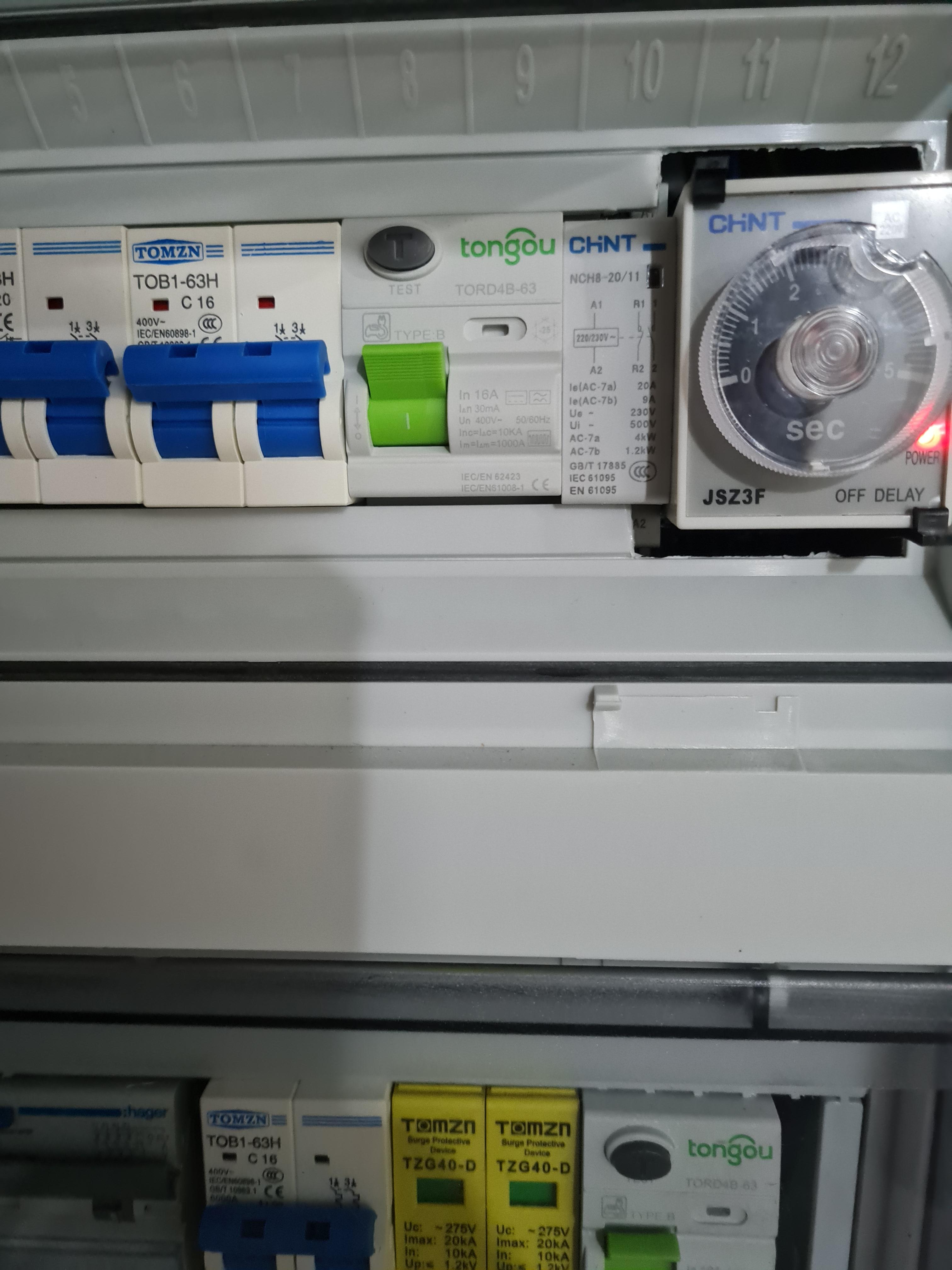
So just an update, I think I solved the problem. As I suspected my N-G bond contactor de-energized (creating the N-G bond on the output) before inverter released its grid relay. Just enough to create two N-G bonds and therefore the output RCD tripped. So I got a "true" delay off timer. They call these "true" because it has some sort of internal capacitor to hold a small current for the delay time, when power is lost. Other off-delay timers exist, but they need an external source of power for internal timer to work. The off-delay timer holds the N-G bond contactor powered (open) for a few seconds, giving the inverter time to release it's grid relay. Now the RCD doesn't trip anymore when I simulate a grid-down situation by turning off the grid breaker. Here is the model I got (JSZ3F with DIN-rail backplate): https://www.aliexpress.com/item/32969613011.html The only downside is that it's a bit bulky for the DB, had to cut out some of the plastic for it to fit. Thanks for all of your inputs. I hope this helps others too.

-
OK, so that seems to be a newer model than mine, but should still work using the same protocol etc...
-
Interesting, I also have a PH-18 (3kw, 24v) and haven't noticed such an issue using SolarAssistant. I'm using Raspberry Pi 4 also, with USB directly connected to the inverter USB port. I have pulled the USB from the Pi and connected to PC, back and forth, never did I need to restart the Pi or the inverter. Can you try to install SolarAssistant on your Pi (on a separate SD card) and see if it gives you problems ? You can install SolarAssistant with a trial license, so no need to buy just for this testing. Have you tried using a different USB cable? Preferably one with a ferrite ring to decrease chance of interference. Also, do you have a good stable power supply for the Pi 4? It's known to be power hungry (relatively that is...) and very finicky when it comes to power supply.
-
There are a few things to address here: 1. Unfortunately, it seems the MUST inverters are also plagued with the "premature float" bug, as in Axpert inverters. So you may be experiencing batteries thahaven'nit fully charged from solar during sun hours, a d therefore not lasting as long into the night. I have played around with settings, but haven't had much success. A partial (not ideal) solution is to set the battery type as LI instead of USE. You can still change float and bulk voltages (set battery type to LI and then change voltage settings). It partially solves the problem, because the charging strategy is different: It charges up to float voltage first, holds this voltage for a while, then charges up to bulk. So it doesn't prematurely float. But there are downsides: First, being that while the lower float voltage is reached, it tends to hold it there for a certain time, taking less power from PV. Second, when it reaches bulk, it doesn't stop charging, it just keeps the battery at the voltage (forever ?) as long as solar power is sufficient. But if you charge from solar only and have conservative float/bulk settings, I think it won't harm the battery too much. Lifepo4 doesn't like to be at high SOC for a long time, but since we are charging from solar, it shouldn't be more than a few hours (depending on how much solar you have). 2. Check setting #28, make sure it's enabled. This will allow you to make the most of your PV production. 3. I find setting #5 to be misleading: Its called "solar supply priority", but at least from my observations, it's not really prioritizing. It simply relies on different voltage thresholds (either setting #20 or #21, in regards to LBU/BLU respectively). So basically you need to choose how much you want to drain your battery, but via voltage settings. When in SBU mode, let's say you set #21 to 26.6v and setting #5 to BLU, it will drain the battery (when no solar) untill around 80% SOC (for Lifepo4) and then start powering loads from the grid. The next day, when solar power is available, it will continue powering the loads from the grid, until battery has reached setting #21. So in short, I find it hard to maximize PV usage with the MUST inverters.