AlexTZA
Members
-
Joined
-
Last visited
Everything posted by AlexTZA
-
We had City Power come and remove prepaid meters from two properties in our complex yesterday. Both have solar. Both seem to have experienced similar to what @Schnavel has gone through - the officials said they suspect the properties were stealing power (despite that you can see the solar panels on the roof) and they will need to prove they are generating their own power/not stealing at council to get reconnected. It's almost certain when you present such evidence at council they will indicate you can't have a prepaid meter with solar. Perhaps they should consider indicating as such on the application form for starters, but it seems that would save people time and money and would be too customer friendly. The one owner hadn't loaded units since installing the meter in December last year, the other had a prepaid meter for many years prior to installing solar. I'm wondering if they have automatic flags on the back-end that looks at units consumed compared to prior consumption over a period like 6 months or something. I went through a period of more than 10 months of buying no units whatsoever and only recently started buying some every month to hopefully prevent the meter removal. Who knows, if they remove the meter it simply makes more financial sense to me to tell them to keep it.
-
100% correct - I forgot about the combined CBI ELR w/overload exactly for the cost reason 😄
-
Check the max fault/fuse circuit rating of the panels in the data sheet. That is the number you need to ensure you do not exceed if there is an electrical failure of a panel in a string that could cause current from the other strings to flow in reverse through the faulty string. If the fault current isn't specified, stick to not exceeding the panels short-circuit current rating - hence normally the rule for fusing above two parallel strings.
-
@Scorp007 Maybe my choice of wording wasnt the best. Both isolators and circuit breakers obviously disconnect power. Breakers are for automatic safety. Isolators are used for safe permanent disconnection of parts of a circuit. Probably due to the physical construction/design of a circuit breaker, they are not considered as safe permanent isolators of power. SANS requires an isolator for safe permanent power disconnection for maintenance etc. Some switchgear is rated for isolation as well as breaking. A good example of this is the traditional CBI main switch which has a mixed white/green switch handle (white meaning breaker, green for isolator). Similarly, a CBI earth leakage switch has a green handle, indicating it is an isolator and can used as such if protected by a breaker. Here's a decent summary of the difference I found online: https://www.beny.com/isolator-vs-circuit-breaker/ The withstand current rating I believe you are referring to (usually 3/6kA) is the peak current the device can disconnect/withstand for a short period without being damaged, usually under short circuit conditions. Although the device would have some lower designed trip current, it needs to be able to withstand worst case conditions before tripping without failing so that it can actually trip and do its job. That's why the withstand current will be standardised (3kA residential) for breakers regardless of their rated trip current.
-
These are ok as long as you don't create more than two strings in your array. Any more parallel branches requires fuses per branch to protect each branch from excess short circuit currents that could result in bad things (e.g fire)
-
@Greglsh I'm reasonably familiar with the SANS standards but would still go with the advice of an experienced and trusted electrician, if you can find such a person. They especially need to understand the solar and DC side of things as well which is really the most dangerous part of an installation and unfortunately tends to be rather lacking. The number of installs I've seen where a CoC was issued but the install was so obviously not compliant and/or downright dangerous is rather concerning. Yes, a 63A double pole isolator is fine as that is just it's maximum switchable current rating. This will allow for complete and safe disconnection of power to the inverter in case of maintenance. This board should be mounted within arm's reach of the inverter. The main thing with breakers is they are normally not rated as disconnection devices, hence the requirement for an isolator where all incoming power can be disconnected. Breakers are there to limit current flow to protect downstream cabling from current that would exceed the cable rating. So generally if the size of a cable changes downward somewhere, you need a breaker to protect the cable Happy to hear from a learned electrician master that can school us but understandably most don't like to share their trade knowledge for free.
-
@Greglsh The 40A breaker should be a double pole isolator as the main sub DB disconnect. The SPD and feed cable would be protected by an upstream breaker in the main DB. Note, I'm not an electrician so you should have any installation checked out/signed off by one.
-
@Scorp007 Yes, it appears so, 22W was the inverter consumption. As for manufacturing, haha, yes everything is made in China. The point I wanted to make is related to comprehensive documentation or the general lack thereof of Chinese brand inverters.
-
These sorts of statements speak to one of the major issues of most inverters manufacturers (which let's be honest, are nearly all Chinese), bar maybe Victron. They leave users and especially installers in the dark as to how to fully understand their product.
-
@cp69 You can run without batteries, as shown below. However the inverter needs at least one alternative backup source to provide backup power - either solar panels or batteries. If neither of those are present, the inverter is nothing more than an expensive piece of "wire" connecting grid to the backup side. So until your batteries arrive, you will need to keep your load change over switch in the "Grid" position.

-
It largely depends where the inverter and DB are relative to each other. If they are relatively close (i.e. on the same wall) then the change over switches and inverter switch gear can go into a single board. If not, then you will need one board by the inverter, which contains all the inverter switch gear and one by the main DB that contains the changeover switches. You want the changeovers near the main DB so that you don't have to run an essentials AND non-essentials load cable back to the main DB from the changeover outputs. You'd probably be fine with two 18-way DIN boards if they are split and maybe a 24-way if a single. Rather make the boards a bit too large - easier to wire and add things later.
-
You need two changeover switches. One for essentials, one for non-essentials. As grid and inverter power sources are wired into both, you should get the 63A two pole Hager switch. I would recommend you use 40A input and output breakers (with 6mm cable) for the inverter if you want to to allow the full pass through current. The Sunsynk manuals are a bit of a spastic hit and miss sometimes. If you read the Deye 5kw manual, they recommend 40A breakers on both sides (32A for the 3.6kw version on the load side)

-
I've used the Vestwoods batteries before - can't say anything bad about them considering the price. Have a look at this teardown of the Vestwoods battery:
-
Max continuous AC pass-through current is ~35A for the 5kw so 40A breakers paired with 6 sqmm cable works well. What are the Beny AC surge protector max operating voltage? I'd go for something around 270-280V. Perhaps consider adding both an essentials and non-essentials change-over switch - the latter being useful if you have electric non-essentials like the stove/geyser which you can then choose to manually switch to run off the inverter if necessary (e.g. for extended 24 hour+ outages that are becoming ever more common these days as infrastructure melts down...). Layout kind of the depends where the inverter DB is relative to the main DB.
-
@Telepage Can you describe or be more specific with the issues you are having?
-
@L_D Did this happen out of the blue or after you adjusted some settings? Are you sure the backup port is enabled as if this is off, it results in exactly what you are seeing? Local config -> Smart Port -> Backup Port Enabling Setting = Enabled When off:


-
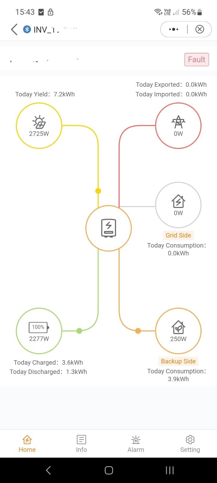
@L_D Yes, the firmware and app are definitely a work in progress. To be fair, the early days of the Sunsynk interface also had some interesting moments and wobbles. Can you elaborate as to what issues you are seeing so that I may be able to validate on my end? I noticed when looking at the installer-view remote settings that the Meter/CT settings didn't match the local Bluetooth settings for the Meter Type (Meter in Grid Eastron Std 1P Meter vs No Meter) and CT Ratio settings (0 vs 2000). I tried changing the CT ratio remotely and it didn't change so I suspect the remote settings are broken. So the values I've listed below for the CT values are the local equivalents. Work Mode = Self-Use Mode Self-Use Mode->Self-Use Mode Switch=Enabled Self-Use Mode->Time of Use Switch = Enabled Self-Use Mode->Charge and Discharge 1-3->Time of Use Charge Current Set=50A Self-Use Mode->Charge and Discharge 1-3->Time of Use Discharge Current Set=135A Self-Use Mode->Charge and Discharge 1-3->Charge Time Slot 1 = 22:00-08:00 Self-Use Mode->Charge and Discharge 1-3->Discharge Time Slot1 = 08:00-22:00 Self-Use Mode->Charge and Discharge 1-3->All other time slots not defined Self-Use Mode->Charge and Discharge 4-6->All times slots not defined Self-Use Mode->Allow Grid Charging=Enabled Self-Use Mode->Battery Reserve Switch=On Self-Use Mode->Reserved SOC=80% Self-Use Mode->Grid Charge Power Limit=2500W Meter/CT Setting->Meter/CT Setting=CT Meter/CT Setting->Meter Type and Installation Location->Meter in Grid NO Meter Meter/CT Setting->CT Direction=forward Meter/CT Setting->CT Ratio=2000 Battery Setting->Battery Type=Lithium Battery Setting->Battery Model=Pylon_LV Battery Setting->Max charging current=125A Battery Setting->Max discharging current=125A Battery Setting->Overdischarge SOC=15% Battery Setting->ForceCharge SoC=10% Battery Setting->Battery Healing SoC=100% Battery Setting->Peak-saving setting=Off Battery Setting->Max.grid power when force charging=500W Battery Setting->ECO Function=off Battery Setting->Battery Wakeup Switch=off Battery Setting->Auto Bat Awaken=off I also did a quick check of the non-essentials side again, given changes to the firmware since the first post. In principal, the no-grid feedback aspect is working mostly as expected, but I did encounter some oddities. Bear in mind I'm basically operating the inverter in an off-grid setup most of the time, but the current setup is as such that I can turn on the grid-side isolator and reconnect if required for battery charging and other experiments without exporting power and other untoward things happening. Based on the local Bluetooth power flow view, here was the starting point prior to grid connection: After enabled the grid connection with my battery at 100% SoC, the first thing I noticed is the solar suddenly came to life and starting charging the battery? This went on for a few minutes. Looking at the BMS battery info, the battery then charged to the required maximum Pylontech float voltage, whereas before it was clearly not at that voltage without the grid connection which is not right. I will have to investigate further another time. On enabling the grid connection, the grid carried the entire load for a while. Then, the solar slooowly started ramping up - actually it was painfully slow until the solar totally took over the load supply. I did some investigation and it appears you can adjust this response rate which I think is overly conservative. In the local Bluetooth connection settings, go to Grid Code Setting->Advanced Setting->Power Limit->Power Change Slope Limit and change the default from 10% to something higher (I used 50%). I wanted to do a bit more correlation with what was happening on the app cloud view but then load shedding kicked in so that ended that. Other items I've run into before but bear mentioning: - If you walk out of Bluetooth range of the inverter, the app obviously loses connection with the inverter. It periodically indicates that it's trying to reconnect but even with me standing next to the inverter, it never does, which is rather annoying and it would be great if it would just reconnect on its own. - I see there is now a Device Upgrade option in the app which is great news - well at least for me. This allows you to check for newer versions and update the firmware of the inverter yourself without having to send a request and wait for someone in China to do it for you at a most inconvenient moment (ahem...Sunsynk). Hopefully Solis is super confident that this won't result in trouble with bricked inverters 😄. - Still no SoC-type timer functionality in the inverter Work Modes yet unfortunately.


-
@Skusku You can set up zero export and I did test that it works as long as the CT coil is installed correctly. I should point out that not all prepaid meters have issues with small amounts of reverse power flow, especially the newer ones which are probably designed for this possibility in mind. For example, I have a 1 year old prepaid meter (AMS S12U16) and while I was testing the Solis inverter, the CT wasn't installed the right way round so 6kw was exported to the grid for a few minutes. I believe most newer meters just bill you for the power flow in either direction and in my experience, in JHB anyway, I have yet to have experienced an installation where a prepaid meter went into any kind of protected mode due to transient inverter feedback. Maybe I've just been lucky 😀.
-
Can you provide a screenshot of the settings? Are your firmware and app the latest versions?
-
Well this a bit confusing model name wise, but the cheaper inverter is a grid-tie only inverter, i.e, it only has PV inputs and cannot be connected to a battery i.e it cannot be used as a UPS. So it's the PRO inverter you want.
-
I don't really see why using a particular brand of battery should void an inverter's warranty as long as they are the correct voltage. The inverter and battery communicate via the BMS, or if not, the battery is just operating by voltage, but in either case the inverter is always in control of the battery. The main issue usually relates to the BMS comms and if the inverter manufacturer has validated a particular battery works with their inverter. As mentioned above by others, many batteries support the Pylontech BMS protocol and if they do, will work fine with the Solis.
-
Great, looking forward to the feedback!
-
@JayMardern - I've found its best to speak to Deye if there are any technical questions as I've found Sunsynk support to be somewhat...limited, especially around topics that are not clear. I usually send an email to [email protected] which is the main support email address listed on their website. It sometimes takes them a while to respond.
-
I specifically emailed Deye about using the Aux port in parallel for a generator input and they said you can do this. I have since connected multiple large diesel gensets to paralleled Sunsynk 8 and 12kw inverters without issue. In fact, the inverters won't use the power from the generator if it is only connected to one inverter input in a parallel configuration. I can't comment on the paralleled aux output but have seen the recommendation not to do so. So as a potential workaround if you want to use the aux as an output (which is basically on the load side anyway), is to use the aux port from one inverter as a contactor signal only to leverage the logic. Thus, you use aux port to switch on/off the contactor connected after the parallelel load breaker to power your "smart" loads.
-
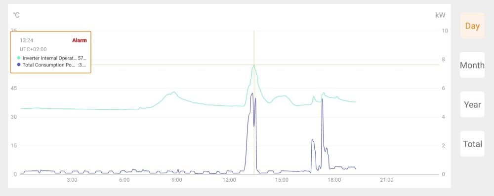
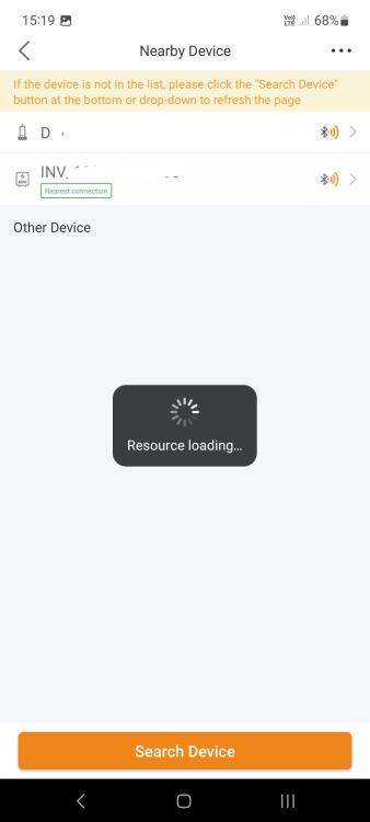
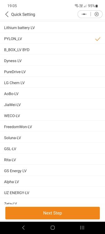
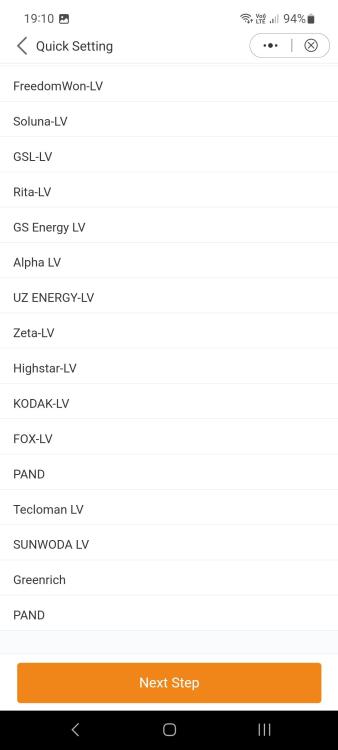
@cp69 Thanks, glad to hear the information has been useful. I have no desire to be a brand ambassador though, just trying to be objective and hopefully that's useful to others. On to some other info. - While I was busy discharging my batteries to get them below the minimum settable battery SoC for the generator to be usable (90%), I had a substantial load running on the inverter for about 45 minutes, that included my geyser, aircons and an electric hob plate or two. I noted the inverter internal fan was switching on when the load was higher than 3kw and off below that. Here is a graph of the load and resulting internal temperature,y which peaked at just over 57 deg.C. Generally the temperature tends to sit at between 30 and 35 deg.C. - There is an interesting issue with the Solis app where if you have no Internet access, you can't seem to connect to the device locally to configure it. I tried a few times of restarting the app and waiting a fair while but it gets stuck on the screen below. Easy enough to get around with a mobile data connection via your phone, but still somewhat bizarre to require an Internet connection to perform local Bluetooth configuration. - The inverter is currently connected to Pylontech batteries and I wanted to test it with a Greenrich battery, which I have been told by Greenrich is compatible the Pylontech BMS protocol. As I didn't see it listed in the settings area for batteries, I simply left the inverter in the Pylontech setting and the BMS worked perfectly with the greenrich battery. However, the inverter didn't want to enable the load output and on investigation I could see there was some strange bus voltage alarm. After reviewing the battery parameters displayed by the inverter, I could see the high voltage charge protection value I had previously set to 53v for the Pylontech was probably the issue as the Greenrich was already above that value. However, I could not find the setting anywhere in the settings menu indicating it was probably removed at some point. I eventually ran the Quick Setup again which actually has a much longer list of supported batteries (including Greenrich) than the settings menu where I was looking. Here's the current list. I suspect Hubble batteries will also work with the Pylontech setting.