Snuffleupagus
Members
-
Joined
-
Last visited
-
-
-
-
-
Eh... not officially. 😉 They only sent me the compiled program, but since it is made with .NET I was able to decompile it with ILSpy to see the code. I needed to understand how they make the protocol level messages since I want to make my own monitoring script.
-
-
-
I contacted [email protected] with my questions and got a response containing monitoring software that they use with their batteries. You can find the files here: https://drive.google.com/file/d/1hSka8UvoSMR2WizIR3u58ZHuIAa3Q9Xh/view?usp=sharing Looks like "MYCanProtocol/MYBMSCanProtocol.cs" is the file with most of the protocol decoding info for both CAN and RS232. With the software you should be able to read info like cell voltages and alarms. I am trying to port some of it to NodeJS so I can run it on my Raspberry Pi, since that is already monitoring the inverter.
-
@CobusK Sure, here you go: https://drive.google.com/file/d/1hSka8UvoSMR2WizIR3u58ZHuIAa3Q9Xh/view?usp=sharing What they sent me was the monitor software and manuals. From there I used ILSpy to get a look at their code and get an idea of how they interpret the RS232 / CAN messages. Looks like "MYCanProtocol/MYBMSCanProtocol.cs" is the file with most of the protocol decoding info. The compiled software is in the "3 Dyness monitor 220331" folder. I am not sure if they have a specific SA support branch. I just contacted [email protected] with my questions and got a response from Lane Liu ([email protected]) at their R&D center.
-
-
-
I have Dyness batteries and they seem to be doing fine. The build quality looks good (from what I can see on the outside) and I have had no problems at all using them with my Sunsynk. Although I have a recent installation, so I cannot say much about their long term performance yet. The Dyness support team is also very quick to respond. I asked them some technical questions about their RS232 protocol and they sent me the documentation with details and monitoring software.
-
Snuffleupagus changed their profile photo
-
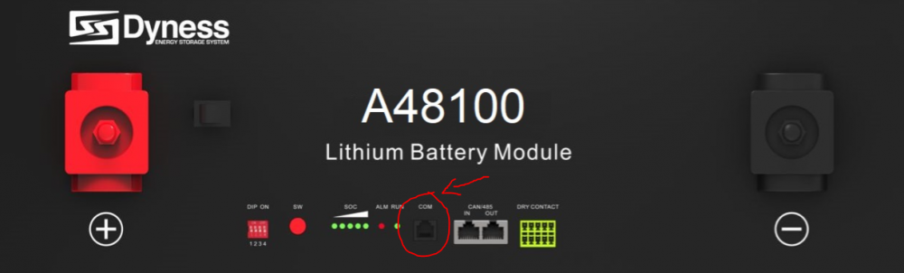
Good day people of the forum, I would appreciate if some of the technically enlightened on this forum could share some advice or experience on a challenge that I am currently facing. I recently set up a Pi monitoring solution for my Sunsynk inverter, querying the modbus registers via a nodejs script, then scraping with Prometheus and graphing with Grafana. All of that is working 100% and I am very happy with the setup. However the inverter's info on the battery is very minimal. It reports the SOC, total voltage and temperature. I was wondering if I could extract some more detailed info from the BMS itself, such as individual cell voltages. The battery I have is a Dyness A48100. It communicating just fine with the inverter via its CAN port. But I see it has a second com port (6P4C) that according to the manual uses RS232: So I crimped a 6P4C connection according to the pin diagram in the manual, and connected it to my RS232 to USB converter. However I am getting no response from the battery with my usual diagnostic test. It also didn't seem to respond to modbus queries. Swapping the RX and TX pins also didn't help. So now to anyone who may know: what kind of com protocol does the Dyness BMS use? Does it require additional configuration that I might be missing? I would be grateful if anyone has some protocol specification I can take a look at.
-
Snuffleupagus replied to Snuffleupagus's topic in Starting In Solar? Feel free to introduce yourselfThank you everyone for your insights. I see there was quite the discussion about the split neutrals... but as far as I am concerned the matter has been settled for me. Combining feedback from various sources I have updated my wiring diagram a bit, this time only looking at the AC side (since the DC / PV side is quite straightforward and seems to be fine): In the setup above I have hopefully covered all the modes of operation that I will need to support. I might have gone a bit heavy on the SPDs though... I have one now at my main db, another one right at the inverter input (which might not strictly be necessary given the main db one), and one on the inverter output (to protect against spikes on the load circuit going back into the inverter). But I would rather have more protection than needed, than not have enough. So now there are mainly 2 things that I need to clear up... I want to use an industrial type socket / plug combo as indicated in the diagram to connect the inverter power station (which is mounted on a standalone steel frame with batteries) to the house wiring. Is there any kind of regulation that would prevent me from doing this? Important to note here is the socket will be before the main RCD, but it is not a general purpose socket and will only ever be used for the inverter. Also, it is really hard to find these types of sockets rated above 32A. How much of an issue would it be to use a 32A socket/plug with a 40A (theoretical max) circuit? The next step up would be 63A, and those plugs are a lot more expensive. My house is quite old, and there is one sub db that I would like to keep without modifying. However it has 25A breakers on the plugs. According to my understanding the max breaker you are allowed for normal sockets is 20A... would this be an issue? Or can it stay that way since it is part of the existing installation? Thank you to everyone who shared feedback - I appreciate it.


-
-
-
-
-
-
-
Snuffleupagus replied to Snuffleupagus's topic in Starting In Solar? Feel free to introduce yourselfThanks for everyone's responses! Since I have posted this diagram I have received the following advice from various source, so consolidating it here: I was recommended to move the inverter AC grid input before the main RCD, not after as shown in the diagram. The reasoning being that power going back from the inverter to the main circuit should also go through the RCD to the rest of the circuits, and that inverters do not need to be on an RCD protected circuit themselves. As it is, the power fed back from the inverter bypasses main RCD protection. Downgrade the inverter CBs to 40A. This was due to having 6mm2 wiring, and a 63A breaker would need at least 16mm2. But apparently when you have a 40A breaker you can just barely get away with using 6mm2 wiring on that circuit. Move the changeover switch to the main db instead of the mobile "power station", so when the station is physically disconnected the essential load circuits can still be bypassed to the main grid. (This was an oversight on my part in the original planning.) Move the inverter input SPD after the inverter main switch, and optionally add an additional SPD on AC load if the circuit extends outside the house. This is indeed the case for me since I have the gate motor and outside lights on it... apparently lightning can cause pulses on any outside wiring which could feed back into the inverter. Not sure if it's overkill having 2 SPDs? But the explanation made sense. A bit pedantic but important nevertheless - the actual wiring for neutral needs to be black. (The diagram just uses blue to visually distinguish it from the DC wiring.) OK, so my question about connecting the neutrals has been answered. Thanks! Now all that's really left is to figure out how to connect the "power station" through an unpluggable interface. The largest sockets I found only carry 32A, but I would need something that can handle 40A at least... and there are 5 wires that need to be connected through whatever interface (AC grid L & N, and AC load L & N, and Earth).
-
Thanks. I suspected that would be the reason that I did not see many alternatives... Do you know how to get access to the relevant regulations? I would also like to learn what the rules are regarding these installations. I've met too many unreliable electricians to be trusting them without learning things for myself as well.
-
-
I have a Sunsynk 8kW inverter and am using the ATS output to power a relay that connects neutral to earth when the inverter is operating in off-grid mode. My understanding is that this is to prevent the neutral from floating away from a "safe" earth reference while the grid supply is off. Now I have been thinking about this, and am wondering if there is another acceptable way of doing this. I sadly do not know much about laws and electrical code, so perhaps someone can enlighten me on this. But my idea was to use a TVS diode instead of a relay to keep the neutral tethered to an earth reference. Let me explain. If the neutral is connected to earth in a permanent way, the earth leakage trips on my side (which is expected, since there is a slight voltage difference). But what if I use a bidirectional TVS diode between earth and neutral - one that would not conduct at the usual difference, and would clamp the voltage to around 10V or so? That would prevent any tripping when using grid power, and would keep the inverter neutral from going further than 10V from earth. Would this satisfy the same safety requirement that the relay is doing? Also, for my curiosity, what are the hazards of letting the inverter neutral drift? From what I can tell both neutral and live wires are well insulated and do not come into contact with exposed surfaces. I like this idea for several reasons: It does not have the power usage of keeping a relay turned on. It is a solid-state solution which could theoretically last much longer than an electromechanical relay. Most importantly, it frees up the one ATS output I have on my inverter so I can use it for other things. Any input and insight from other members would be appreciated.
-
Greetings people of the forum! I have been planning my solar power system for a while now and purchased most of the components. The installation is 100% DIY, so I am going solo on trying to figure things out. Now I am at the point where I need to map out how the wiring works... Here is my current attempt at a wiring diagram: Since the forum contains members far more experienced and knowledgeable than I, I'm throwing this out there to see if anyone has something to add before I go ahead. Am I missing something important? See something that won't pass CoC? Any comments will be appreciated. In the diagram I omitted the main db circuits (lights, plugs, etc.) since they are already there (and approved compliant) and won't be changed apart from splitting the db into essential and non-essential. I was also wondering about needing to split the neutrals for essential and non-essential circuits. The inverter manual wasn't really too clear on this (or perhaps I missed it), but I am keeping the circuits separate in my diagram. Would it be an issue to combine the neutral bus for AC Grid and Load? Lastly, this design keeps the inverter side separated as much as possible from the existing house wiring, connecting AC Grid and Load via the labeled connection interface in the diagram with the option to unplug things. This is part of my mobile power rack idea that I am still developing. I don't know what this interface will be yet... anyone here know what connectors I can use? The inverter has a 50A pass-through relay, so I guess it would need to handle at least that much. Thanks in advance for any feedback. The advice and information on this forum has been extremely helpful in designing this system.

-
-
-
While planning my installation of a new Sunsynk 8kW inverter and 3x Dyness batteries, I was considering where to put it. I see the most common approach is to mount everything on a wall with the wiring fixed. But while thinking about it I had another idea, so I just want to throw it out there to see what the forum thinks. Basically it's a kind of modular power rack where everything is bolted to a steel frame, which can then be moved as a unit if needed. Here are some very rough sketches (inverter on top and batteries below): And just the frame alone: While it's not apparent from the images, the battery section is modular and can be extended by bolting on additional shelves. The switches specific to the setup (such as inverter switches, circuit breakers, etc.) would be placed in surface mount dbs attached to the frame. Then instead of wiring it directly to the house, it has large sockets / plugs for making the connection to AC grid and load, as well as PV input. I was thinking of this because I have very limited free wall space. And if you put wheels on the frame it can turn into a mobile power station. 😀 Has anyone here done something similar? What are some of the issues or problems with this kind of approach?


-
Thanks @Dyness and @Gnome! Yes, I carefully read the instruction manual. 😀 These can be wired in parallel. Since I am not as experienced with lithium batteries I just wasn't too sure what the extra terminals on some batteries were for, but thanks for clearing it up! I think I like the bolt-on terminal design better. Looks like it will make a very secure connection.
-
-
-
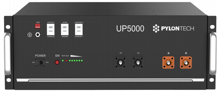
I have a quick question that may sound a bit silly, but it has had me a puzzled for a while now. My batteries arrived this morning (3x Dyness modules): Now looking at the wiring diagram in the manual it seems quite straightforward to wire these in parallel: just connect all the + terminals together on one side, and - terminals on the other. But when I look at other common lithium battery models, for example the Pylontech, I see it has 4 power terminals (2x + and 2x -): So my question, for those who can enlighten me, is why do some batteries have 4 terminals? These seem to have something to do with their parallel configuration, but what is it doing exactly, compared to just having 2 terminals?

-
When I read the Sunsynk manual I had the impression that it could operate as a full grid-tie inverter, i.e. pushing PV power back to the non-essential side of things. Otherwise it would not be coming with a CT coil... so unless I am misunderstanding something I believe the Sunsynk inverter actually has the capability you want.
-
Snuffleupagus replied to Snuffleupagus's topic in Starting In Solar? Feel free to introduce yourselfThank you for everyone's replies and advice! After taking a long, hard look in the mirror, and shedding a tear for my bank account balance, I have decided to beef up the system up-front rather than wait to expand. The way things are looking with Eskom now concerns me. So I eventually decided it was worth it to get as much initial independence as I can afford. Hopefully this will pay off in the future. My new setup idea looks something like this: 8kW Sunsynk 3x BX51100 Dyness batteries (15.36 kWh total) 12x 470W Jinko Tiger (5.6 kWp) I went with the bigger inverter after all, with the idea that it would be more future-proof. The batteries I got on a BF special - I couldn't find a better R/kW ratio so I went ahead and bought them already. Some recent threads have made me a little more hesitant to use the Hubble's NMC chemistry. 😅 These BX51100 models have 0.5C recommended and 0.75C max according to their datasheet. The max draw of the inverter is slightly above the recommended 0.5C, but I doubt the small difference will really cause a problem. Especially since I will rarely, if ever, hit the full 8kW anyway. Now for the panels, does anyone have experience with the Jinko brand? Are they reliable? I found those panels at a better R/W rate than the JA Solar ones I initially thought of, but it's always good to check if anyone has bad experiences with them first. Since this is turning out to be quite an expensive investment, I want to double check to make sure I am not making any mistakes here. Which brings me to another question - does anyone know reputable solar installers who operate in Pretoria North? I still kind-of want to install the system myself, but a lot of the warranty documents I read mention that you need a qualified solar installer... so I'm not sure what my options are here. Since installers make their business actually installing, I don't know how many are interested in just consulting / checking the installation for certification afterwards.