


Coulomb
Members+
-
Joined
-
Last visited
Everything posted by Coulomb
-
So far, the differences between SCC firmware revision 4.10 verses 4.00 seem to be to do with higher current hardware. At the start of main, three bits in port G are checked. If 000, full scale current seems to be 61.2 A as before; otherwise, it's 105.0 A. But it also checks for the pattern 010; if so, a new variable is set to 1 (and otherwise cleared); this seems to set some current limit to 80 A instead of 60 A. The fact that Rev 4.10 was supplied with an older model SCC indicates to me that these bits must be set to zero in older hardware. In other words, it must be safe to use the new firmware in older hardware, despite the fact that the newer hardware is capable of more current, and the older hardware is not. I spotted a temperature limit going from 70°C to 85°C, so the higher current hardware must also run hotter at maximum load. As to whether any minor bugs are fixed, it's impossible to tell at this stage. I did notice a comment of mine where I decided that they'd made a benign error in their source code, and it wasn't fixed in 04.10. So they're not superhuman (It's also quite possible that I've made a mistake there; I didn't look in detail this time around.) The function I'm most interested in (which I call AdjustChargeStage) hasn't changed at all. This is the one where they decide when to change from bulk to absorb and absorb to float. So it looks like they are at least making provision for a 100 A SCC in the future. Otherwise, why change the shunt to just over 100 A from just over 60 A?
-
Wow. You don't see much through-hole electronics like that any more. That could be a part of why it's so expensive - using more expensive PCB assembly methods. I'm not saying it's bad, just unusual to see these days.
-
At this very early stage, yes, it looks that way. But if you can hold off for a while, things might get a little clearer.
-
Sorry guys, I don't monitor this topic much (mainly the Inverters one), so I rely on notifications because someone mentions my name. And you did (thanks!) but I was slack and didn't check notifications. But today I've had a quick look. So far, the main firmware changes are very few. In fact, the code follows the exact same addresses right up until the version number is printed out in a QVFW command. They do it in two chunks; the "0007" part and the "2.60" part. The latter is printed as a decimal number, with one digit before the decimal point and 2 digits after. So the immediate constant was 240 for 72.40, and it's 260 for 72.60. Guess what? 240 is less than 256, so the compiler can compile a one-word instruction to move this into the acumulator. But 250 is >= 256, so it has to use a two-word instruction with the constant 260 (0x0104) in the immediate field, in the second word. So the addresses all start to diverge at that point. This makes my high-tech comparison method invalid. What I do is look at one disassembly, use alt-tab to flip to the next task, which is always the other disassembly, and check for any differences. I flip them multiple times; after a while it becomes easy to spot any differences. (Did I mention that this was high tech? Don't try this at home ). I hope @plonkster and the others appreciate that little tech story. So now it's a pain to check for differences after that point, because the addresses are different, the eye sees many irrelevant changes, so any relevant changes don't stand out. Sigh. So I did the same with the function names window. It turns out that there is exactly one new function, named _sQFTYCommand(). The leading underscore is a C compiler thing; it's so that C function names can't clash with assembler function names (unless you named it that way, and they assume this is unlikely). All the Commands (routines that respond to commands from the PC port) start with the command mnemonic and end with Command. So this is the QFTY command [ Edit: actually QFTY5200, no CRC); this likely stands for Query Firmware ? ? . (Many commands start with Q for query or P for setting Parameters). I don't know what the T or Y stand for. What the function does is to print "VOLTRONIC POWER TECHNOLOGY CORP." and a carriage return. The usual leading open parenthesis ("(") and trailing CRC are omitted; they go to the trouble of turning off the _wCRCChkFlg flag to suppress the CRC (this happens in only one or two other commands; that means it's quite rare). My suspicion is that they are getting tired of having clones of their firmware turning up in knockoff competitors' machines. I'd say this is designed so that they can power up a competitor's machine in court, have it print their company's name, and have the prosecutor's lawyer yell "I rest my case!". Well, that's pure speculation on my part. So: nothing exciting there, unless you are involved in Voltronic knockoffs. I sure hope that this isn't anything to do with firmware patches As for the SCC firmware, it's much harder going for me. Even the main() function has changed, so there could be significant changes there. It will take me weeks or months to figure out what they are, and I may not be able to describe the effects.
-
Actually, there are two UART ports, one for the PC and one for the SCC. They bit-bang to talk to the LCD display. (I don't know about the buttons.) CAN (Controller Area Network) is used for paralleling comms.
-
I like to keep a small profile about that (if that's possible); asking only where I have a need. That would be a yes
-
[ Edit: my apologies; I somehow managed to not see about 100 posts between there and here, and I see that SuperDIY has addressed most of this already. ] Err, no. They only use capacitive droppers in very small power supplies. Never with SMPS. > From there it goes into the (rather small!) transformer in the red, It's rather small because it's switching at high frequency, 15-100 kHz. That's why it's powdered iron or ferrite (I never remember the difference with those two) core, not iron laminations that you always see with 50 Hz transformers. > and then it is turned into DC by the four diodes also in the red. Those four diodes are turning direct 230 V mains to ~ 325 VDC. That's why it's rated at 400 V. There is another diode (or two or four) at the output. > Big electrolytic tank to make it smooth. Well, if you call 68 uF big. This type of power supply can't operate over a wide range of input voltages, so this capacitor is needed to provide power while the mains is away from its peaks (~ 95% of the time). > Then it goes into the SMPS, which is in the blue block. That is, two stage PSU, first drop the current with a cap, then drop the voltage somewhat with a transformer, then do the rest with an SMPS. No, it's all done with the SMPS (Switch Mode Power Supply). Here is the first typical power supply schematic I found: Note the fairly large capacitor directly across the mains (after the fuse, which the one in the photo doesn't seem to have). It would be the equivalent of the green capacitor in the photo. That and the common mode choke (at the left, in red in the photo) are to filter out switching noise from getting into the mains. If it was to filter out mains from the mains towards the power supply, the capacitor would be on the other side. They probably care about this switching noise exactly as much as regulations force them to. Sorry about the non-English text; it was the first one that had the features I wanted (it's amazing how many SMPS topologies there are). These days,the switching would probably be controlled by a SMD (Surface Mount Device) chip under the board. This one mentions 0.7 mm, probably the size of the air gap. So this one would be a fly-back type. That's why the turns ratios would indicate about 50 V at the output - the control circuit makes sure it never gets that high, by pulse modulating the drive to the transformer (which is more like an inductor, but let's not go there). So the issue in this case, as far as running from modified sine waves (= square waves with the right peak mains voltage) is the input capacitor. If it wasn't for that, the circuit would be rather happy with the square waves. There would be a peak of current into the capacitors, as with mains, but a smaller magnitude, and after that peak, the square wave would actually supply power to the load with a better power factor that from a sine wave mains. I suppose you could just remove the capacitor, and take the risk that high frequency switching pulses won't get into the inverter or other 230 V loads. [ Edit: or add an inductor to the input, where the fuse is in the schematic above.] [ Edit 2: I forgot to add that I don't think that a 1:1 transformer, as someone else mentioned, would solve any of these issues. The transformer would pass the square waves through essentially unchanged, and it would risk running into saturation. ] [ Edit 3: I believe that the 2n2 capacitor above is being used as a dropping capacitor, to provide power for the control circuit. It's a bit obscure, but I couldn't help mentioning it, to point out the contrast. The drive circuitry uses only a few percent of the total power; it's all losses. ]
-
Just speaking in theory here, I have no experience with modified sine wave inverters. Many devices these days have EMI filters on the mains input. These include some X capacitors across the line (line to neutral). These will suffer continual spikes of current due to the sharp rise and fall times of the inverter output. I'd say that this will cause those capacitors to fail, likely open circuit as designed, rendering the filter useless, but until then stressing the inverter and any chokes between the inverter and X capacitors. (Any such chokes will however mitigate the spikes somewhat). Elcon (TCCH) chargers have a large 2.2 uF capacitor right across the mains, before any filtering. I think that this is for correcting the slight inductive power factor of the PFC (power factor correcting) front end. Finally, that's another concern: anything with a PFC stage is not going to like MSW. I've seen some spectacular charger failures (not Elcon/TCCH) that I suspect happened from running off MSW inverters. The trouble is these days even your shaver might have a tiny PFC chip in it. Even if you can open it and read the chip number, some of the Chinese chips (and nearly everything is made in China, often with Chinese manufactured chips now) are hard to find data on.
-
Yes, on my part, sorry. I was assuming you could not get to the thermostat contacts directly, just the thermostat and element series combination. I also somehow managed to overlook the extra relay. What you suggest is of course perfectly valid.
-
I'd say the original poster must have connected to the grid, to see even an error message. I'd say it is able to power its microcontroller from the grid he has, but the microcontroller must have decided that the grid voltage is too low to invert into. It would only need a few watts to drive the microcontroller, display, and associated electronics.
-
428 V is only 1% higher than the bare minimum. You might find that say phase A to phase C is only 422 V, under the limit. This will vary from minute to minute as loads come on and off, many nowhere near the inverter. Usually, specifications on the label are absolute limits; you likely won't be able to go past these limits by changing software or configuration. I think you've been sold the wrong inverter. For example, 24 000 W is about 4 times the largest inverter for a house, and possibly 8x to 12x the average inverter. Is this for a community, or a large farm? The panels needed to feed this beast would not fit on a single house's roof.
-
Sure. But there's not much point if the thermostat contacts arc out open circuit after a week and you have to replace them anyway.
-
The specification label says 423 V minimum (I assume that's phase to phase). So that's 423/sqrt(3) = 244 V phase to neutral. That might actually work most of the time where I live, but it would not be reliable. It will also need to see all three phases, so it can see the 423 V or more phase to phase. Edit: so unfortunately, this won't work in your country.
-
I don't get how this is safe, unless you are relying on the thermostat never switching off. Do you turn up the temperature setpoint, so it never will? How does the geyserwise sense the water temperature?
-
Do you actually have 480 V 3-phase to connect it to? That's a big inverter. Most countries have 380/400/415 V 3-phase.
-
It's actually "HS" in the firmware. "S" and "5" have the same 7 segment representation, as do oh and zero, "Z" and "2", but you can tell from the binary "string" in the firmware what it was intended to be. I've sometimes wondered what HS stands for. Perhaps it was meant to me "MS" for MaSter, but the representation for M is poor - basically the bottom three segments of the "H" . So perhaps the programmer thought the representation for "H" was actually better at suggesting "M" than the representation for "M" itself. (Even though native English speakers tend to immediately see a capital H.) So that's my best guess - this is supposed to mean MaSter.
-
I'm pretty sure it's quite common. For example Solamahn (who isn't in Australia, but frequents the AEVA forums): http://forums.aeva.asn.au/forum_posts.asp?TID=4332&PID=57466&title=pip4048ms-inverter#57466 "I have had no problems with the 4048ms scc even with 15 x 280w connected 5 x 3 and all facing the same direction. " So that's 4200 W nominal of solar panels. Back then, all SCCs (solar charge controllers) in the PIPs (like your Axperts) were 3000 W capable. So that's a 40% "overclocking".
-
Same: no current to the battery, no damage to the battery. Let's say the 32 V is the array voltage, and it translates to 30 A at 26 V at the battery voltage. You can think of electrical current as electrons flowing through a wire, the wires being like pipes that can carry current. It's not totally accurate, and conventional current flows the opposite direction to what negatively charged electrons wouuld flow, but this model is good enough for situation. So the rate of electrons from the charge controller is many squillions (like ten to the 24th power) per second, and we convert from such an unwieldy number to amperes on our meters, and in our heads. So we call it 30 amperes. The load on the inverter, in your exact scenario, is also 30 A. So that means that every electron that comes from the charge controller, goes off to the inverter to power the load. There are just none left to flow down to the battery. Now let's suppose that the load decreases, such that the inverter is now only drawing 28 A, while 30 A are still coming from the charge controller. That means that there are 2 A that have to flow somewhere. If they didn't, the charge would start accumulating at the junction. The junction is like a very small capacitor; there might be say 20 pF of capacitance from all the cabling to battery negative. That's so small that at 2 A, the voltage across this capacitance would start to climb extremely quickly. Like about 1 volt every picosecond (or 100 V per nanosecond, or 100,000 V per millisecond, or 100 mega-volts per second); that's very fast. This increase in voltage will cause the battery to look like a good place for those two amperes to flow. So in reality, the voltage at the node that has the charge controller output, the inverter input, and the battery, increases a tiny fraction of a volt, just enough to cause the two amperes to flow to the battery. So now current into the node is zero again (30 A going in from the charge controller, -2 A into the node from (= +2 A going out of the node to) the battery, and -28 A into the node from (again, = +28 A to) the inverter. That's Kirchoff's law: current into a node must always sum to zero. Even if there is a capacitor there, you can make the capacitance explicit, and the law still holds. We say that the excess solar current is being used to charge the battery. One more scenario to complete the example. Suppose the load now increases such that the inverter is drawing 33 A, but again the charge controller is still outputting 30 A. Now there is a shortage of electrons; the inverter is sucking them in at a rate of 33 amperes, but only 30 A worth are arriving from the charge controller. You can guess where the other three amps has to come from - it will come from the battery. Again, the unbalance of currents this time causes our 20 pF capacitor to discharge slightly, making the node voltage decrease (this time), so there is incentive for electrons stored in the battery to "roll down the hill" from the battery to the node. We say that the battery is providing the deficit between the solar input and the inverter output. The other key concept that beginners need is that even though there might be say 25 A at 32 V available from the array due to the amount of solar energy falling on it, the controller doesn't have to draw that current at any particular time. Suppose the load is very low, and the inverter is only drawing 5 A. Sure, if the controller let it, the 25 A at the array (30 A at the battery voltage) would mean that 25 A would flow into the battery, charging it. If it's full, or is of a size such that 25 A would damage it, then that's not good. But that's why we put smarts into the charge controller. It should sense what the battery needs, and adjust its output so that the battery isn't overcharged or otherwise damaged. That's one reason that an integrated solution like the Axpert has an advantage; it can be aware of the battery current separately to the charge controller's output current. For a stand alone charge controller, this may not be possible, so it might not provide all the available solar power if the inverter is using some or all or more than all of it; the charge controller thinks it's all going into the battery. Another example. Suppose I have a small battery pack that can safely be charged at 20 A maximum. Suppose the inverter load is high, 50 A. I have a stand alone charge controller that isn't aware of the inverter's load. I have a huge array, capable of 60 A at battery voltage. Battery is at 50% SOC, so I'd like to charge it. Since the inverter is using 50 A, I'd like to output all 60 A from the charge controller, so I'd have the left-over 10 A for charging the battery. But I had to limit the charge controller to 20 A, because if the load is zero from the inverter, that's what the charge controller has to limit itself to. So I have 60 A available, but I'll only be supplying 20 A, so instead of charging the battery at 10 A like I'd want, it's discharging the battery by 30 A instead! With a correctly set-up Axpert-like system, I would instead be using all available 60 A (at battery voltage) of solar current. This is a bit of an extreme example; I should not be using such a small battery. Hopefully, I'd be using a battery that is large enough that I don't have to limit the output current of the charge controller at all, so then this advantage (of an integrated system) goes away. I hope I haven't confused everyone with the extra scenarios. [ Edit: I don't read all these posts; I usually limit myself to the inverters forum. So my apologies if this has been discussed already. ]
-
The skipping over happens in the inverter. It doesn't go into and out of the battery at all; the Victron saying zero current into/out of the battery is not lying. There isn't even much clever happening in the inverter to make this happen, it's basically Kirchoff's law (currents into a node must sum to zero). Well ok, the clever part is the solar controller supplying just enough current to balance the load. After that, nothing flows to the battery automatically (in accordance with Kirchoff's law). If you like, the battery is in parallel with the solar charger output and the inverter's DC input; it isn't actually or nationally in series between these elements.
-
Looks like it's the same on all models. From the mentioned service manual.
-
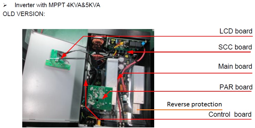
Oh right. Doesn't leave much room for operator error, really. Hard to say. The Axperts have a circuit to prevent problems with reversed battery connections. I've never tried it (would you risk it intentionally?), but it's comforting to know it's there. Though it means that the whole battery current goes through four MOSFETs. On the older models, these were on a heat-sink by themselves, just 43 mm long, in line with the shorter of the two main heat-sinks and separated by a few mm from it. The only thing I can think of is transients on the battery cables, through the power-on surge initiating ringing. But if this was a problem, or even if the suppliers were authorised to use it as an excuse to charge for warranty repair, then there should be a caution about this in the manual. I've never seen any mention of pre-charge in any of the Voltronic / MPP Solar / other manuals. I always start mine with a pre-charge or some sort, either resistive (start with a roughly 5 ohm resistor, then short the resistor with a breaker or suitably rated switch), or I use the single cell method (useful only for Lithium batteries; start with 3.2 V, then 6.4 V (two cells), and move the red cable up the battery, moving quickly from one cell inter-connect to the next, until it's at the positive end. Most useful for temporary connections using car jumper cables, as when testing. The battery management system we're using (our own design) has provision for a pre-charge resistor and associated contactor. It's more expense and wiring, but I feel that the lack of brutality on start-up makes for better longevity.
-
So presumably you set the two units to "PAL" mode (parameter 28) before paralleling them? And verified that the parameter change stuck (seeing HS on one and SL on the other)? This before applying AC input. It seems to me that the Axperts could do with a little more checking before they turn on their outputs. There is just so much to go wrong when paralleling. Certainly others have had misfortune paralleling them, for example: http://forums.aeva.asn.au/forum_posts.asp?TID=4332&PID=56636&title=pip4048ms-inverter#56636 Edit: granted, rather different error messages and behaviour, but both cases all the inverters were non functional.
-
Things might be a little different in South Africa, but surely if the grid drops off, you will have the load of at least a dozen other customers, most of whom don't have finely balanced sources of energy, so you'd always notice it. Of course, as penetration of solar and batteries goes past 50%, you might end up forming a microgrid island. But I don't think there are many places like that yet.
-
There is a marker right at the end of the flash image. On power up, if this is not right, control goes to the bootloader. So it doesn't crash with a half-loaded image, hopefully.
-
¨The worst that can happen is that the flash process might start but never finish. You'd have to be pretty unlucky; you'd have to have a serial interface that was reliable enough to start the flash process but unreliable enough to fail repeatedly. My understanding is that in most situations if the firmware update fails, it stays in firmware upload mode, so you can keep trying again until you succeed. If that kept failing, the unit would effectively be "bricked", like a mobile phone that has had its firmware updated incorrectly. Not really damaged as in parts burned out, but not functional. If that were to happen, you could just get the controller board repaired or replaced. It's a plug-in board; it may cost less than R2000 to replace, if you can source one. But if that's not an option, a ~~R1000 development board from TI with a few mods can rescue it. I have the hardware and software to do this, and hopefully I could guide you through that process through this forum if necessary, but it's most unlikely that it will be needed. A final desperate last resort might be to post just the control board to me or someone closer who can do the update. The control board is only about 250 x 75 mm, so it's a lot easier and cheaper than the main board or entire unit to ship about. Summary: there is little chance of anything going wrong, and there are various options in the unlikely event that something does go wrong.

