Jaxone
Members
-
Joined
-
Last visited
Everything posted by Jaxone
-
YES , that solved the problem. I did not get a notification from the forum but I figured out ... well let's try to switch TX and RX ... and it worked So now I can connect on the Console of each battery, on the US2000 with RJ12 and on the others with RJ45. Now I just have to take the plunge and upgrade the FW.... ChadH360 , I think that is because Pylontech assumes nobody will upgrade the FW on the BMS so newer FW would be backwards compatible ... IF I will upgrade FW we will also test this theory.
-
@pigo I have same problem. If I connect ONE battery pack alone , it will connect without any problems. If I put the batteries in master / slave config , then it won't connect. IF I put an older US2000 Plus as a master then I can connect but I can only see 3 batteries out of 4. I have 2 x US3000C , 1 X 2000C and one US2000 Problem is if I make US2000 as master , one of the US3000C won't wanna join the series. I will try tomorrow to put US2000C as master and see what happens.
-
CAN is faster but are you sure your inverter can connect CAN ?
-
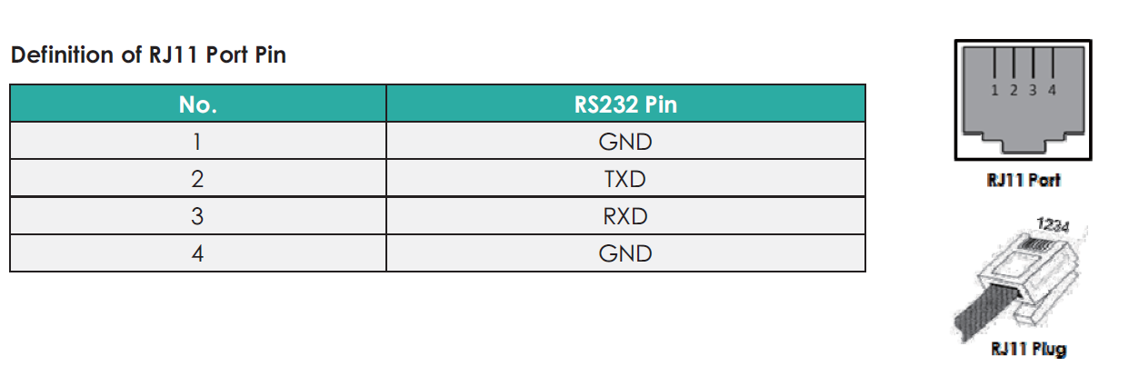
For US3000C I have another cable with RJ45 connector. Connection to US3000C and US2000C works no problem. The US2000 will just not communicate via console. I made RS232 to RJ12 console cable according to manual. Manual says I need to use console with RJ11. ( Port on battery has actually 6 pins , so RJ12) Looking at the battery , only the middle 4 pins are used , so on a RJ12 I won’t use first pin on the left and start from the Pin2 which would be Pin1 on the RJ11 So I am using pins 2-3-4-5 (this would be 1-4 on RJ11). I connect like: RJ11 - SERIAL DB9 Female Connector. Pin2 RED - PIN2 Pin3 GREEN - PIN3 PIN4 YELLOW - PIN5 But I can not connect to it via console L I always get this message from BatteryView :


-
Hello guys. I have 2 x US3000C , 1 x US2000C and 1 x US2000B Now everything works FINE as it is but my inverter will ONLY talk with the US2000B on BMS. But , as US2000B is older than all the others , it can’t be master , tested and won’t work. So the only reason for upgrade for me is to try and upgrade the US2000B and see if I can make it master. Had anyone tested / tried to have the US2000B as master in mixed config ?
-
Solved your problem or did you not got the BMS board yet ?
-
And finally I got an answer from EaSunpower : "Hello my friend, yes, I am very sorry, our engineers are also working hard, Pylontech US3000C, Pylontech US2000C are still in testing, if there is any new progress, I will contact you, thank you." In my eyes this means .... never
-
Aaaaaaaaaaaaaaaand mistery solved ! Today I purchased an older US2000 (don't know software and firmware as this one has the old RJ12 port and don't have a connector for it) and tried to connect the inverter to it and BAM ! Inverter connected to it successfully !! So my issue is indeed the damn firmware in the inverter. I can't use the old US2000 as master battery as the newer ones will not work ... so I must wait for China to provide new firmware for my unit ... if ever
-
Awwwwwww ...... now you hit me .... 🥲 ... and I was so full of hope... I guess i will have to live with it for now and try to find someone else that has this type of inverter working with BMS to see what the problem could be.
-
YES ! The power button os on the right side and does not support Parallel function. So ... any recommended FW for it ? Shall i take the punge again and try to upgrade de FW ? 😀
-
Cable is 100% correct. I checked and 100 times checked the schematics for BMS port on both Pylontech and the inverter. I even made a "bench" cable where I tested all the OLD and NEW BMS RS485 pinouts for bith Pylontech and inverter. Think that I actually did not tried the cable pin mix showed in the posted diagram as Pylontech writes with RED not to use pins 1-2-3 on the BMS port and the cable in this PDF has both ends with 1-2-3 used. So unless some dumbass really mixed hardware inside either inverter or batteries this SHOULD work. Anyway , after I get the RS485 adapters I will test first individually on Pylontech and on the Inverter ... I guess time will tell.
-
I found this document where it shows the 2 jumpers. https://voltaconsolar.com/media/wysiwyg/VM_III_Pylon_US2000_Communication_cable_check.pdf I assumed the board did not changed that drastically over the years and I was right... jumpers are there and they are set up as per document. Don't know what they are for. I also tried to change the position , just to see if there is any change , but no change. @BritishRacingGreen - I did not think to meassure voltage I only tested ressistance and while the inverter and the batteries were trying to make handshake I could see the ohms going up and down. When inverter starts up I think there is 150ohm between the A and B and when I connect the battery to BMS port it will go down to 70 or so. Then when the inverter starts to interogate the batteries it will fluctuate slightly. I'll only get the RS485 today , so after wife and kids go to bed i will start to play
-
Took the chance and open the inverter , even if I broke the seal .. damn chinese don't respond to my mails nor support requests, as expected. Was looking for the 2 jumpers for on the comm board and they are there and seem to be configured correctly also ... so I guess I wait for the RS485 sniffers now.

-
I ordered a RS485 adapter and a CAN Sniffer , want to check if there is ANYTHING comming out of that port in the Inverter. In the manual I see it SHOULD talk CAN and RS485 , does it talk CAN or only RS485 ?
-
If you look into the Pylontech BMS ... they recommend 53.3 ... so 53.2 seems to be viable ?

-
Color of the cover screws are Black. In the meantime I received some information from Pylontech regarding RS485 communication. The firmware on the inverter should be (according to Pylontech ) V1.00/00.32 Also : When compatible with Voltronic Axpert series, only VM III and King two types are availble for RS485 communication, for the rest types of Axpert only available for manual settings.

-
I did reported the bug , I am just curious if anyone else has this issue. Had same issue with older versions of SA also. Tested the same functionality with MultiSIBControl and that one seems to work as intended.
-
Still, from a manual from MPP Solar made together with Pylontech ?? Weird..
-
Found something rather INTERESTING on this manual (updated on 15.1.2021) from MPP Solar in collaboration with Pylontech. http://www.mppsolar.com/manual/Pylontech Lithium/Pylontech inverter setup SOP.pdf Quote : Battery Type US2000B/US2000BPlus/Phantom-S/US3000 As there is no communication between inverter and battery, for a better using experience, it`s also acceptable to introduce monitoring device to visually display the real-time information from battery management system via the communication channel, such as Inverter Control Center(ICC) from centurionsolar. Same as the inverter compatibility condition, such a monitoring system needs get authorization from Pylontech in advance for the compatibility before using with the products from Pylontech mentioned above, otherwise the products from Pylontech will be exclusive of warranty. Change the ‘maximum charging current’, ‘battery type’, ‘back to grid voltage’, ‘back to discharge voltage’, ‘CV voltage’, ‘floating charging voltage’ in the setting page, all these setting must be set to the value listed in below table. Select the right value, then click ‘Apply’ for the changes to take effect. Item Setting Value Maximum charging current Set to N*25A, N=battery amount Battery type Set to USE Back to grid voltage Set to 48V Back to discharge voltage Set to 51V Bulk charging voltage Set to 53.2V Float charging voltage Set to 47.5V " End quote. Float charging voltage Set to 47.5V - Would this be a mistake ?
-
The batteries are 100% charged and Solar Assist is seeing them as fully charged also. If I manually switch to SBU it will switch without a problem.
-
I would rather let it SHOW wrong information than mess my battery pack but yes, I was thinking at this also. Strange enough is that when I run in "Solar First" mode , it shows 100% , only when I switch to SBU it goes down like crazy.
-
Seems the Assistant does not work at all as intended … I have inverter set to SBU , activated the Maintain battery state of charge setting. Connected Solar Assistant to Management port of Pylontech by RS232 and via USB to the inverter. WHILE the Maintain battery state of charge is active and the primary source is SBU I try to override the power source for x amount of time and set it to Solar First.. After this the inverter SHOULD return to SBU … but it does not ??? Or I understood wrong this setting ? Here the video : https://youtu.be/vUwtvxC6wP4
-
Yes , in the manual it says DIP 1 should be on for 9600bps communication on RS485.


-
Reading and reading and reading ... and to be honest I dunno what to say , if it's a clone or a licensed clone .. Voltronic does not specify the licensed brands.


-
Just realized I can't cheat it ... it just uses the FORMULA and not the voltages