


TaliaB
Members
-
Joined
-
Last visited
Everything posted by TaliaB
-
Once an MPPT is active, operating near its minimum tracking voltage does not materially reduce energy harvest. By contrast, placing panels with different shading profiles on the same MPPT forces current compromise and causes large, unavoidable energy losses. Therefore, two independent strings that each barely satisfy the MPPT voltage requirement will consistently harvest more energy than a single higher-voltage string that is partially shaded. If a string repeatedly drops below MPPT start voltage, it will cycle on/off and lose energy. But if it stays above the threshold, even marginally, it operates normally.
-
Bypass diodes only protect cell groups inside a single panel. They do not isolate an entire shaded panel from a string. In your case: Morning: The new panels are shaded they limit string current Midday: All panels clear OK .Afternoon: The old panels shade first same problem, reversed. Because a series string must pass the same current through every panel, the weakest (shaded) panel dictates the operating point. The MPPT can only track one compromise point, not two different irradiance profiles. Put the 2 strings on diffrent Mppt's. Most systems gain more kWh/day by separating shaded arrays, even if each string runs at a lower voltage. Just ensure adequate start up voltage on the 3 panel string .
-
Modern panels typically have 3 bypass diodes, each protecting ~⅓ of the panel. If the same bottom cells are shaded every morning. The affected cell group gets bypassed. Power output drops for that period. Cell damage is usually prevented, as long as the diodes are working
-
@Green Power Makes sense if you want to put them to use for 5 months. How many panels? Maybe do a temporal diy A frame from wood. Something like this, would be more efficient.

-
COCT only cares about changes that affect the grid-facing characteristics of the system (AC side). Pure DC-side changes do not affect the grid and therefore usually don’t trigger re-registration or a new COC. Scenario 1: Add more panels to the existing inverter (within inverter limits) No re-registration required No amended COC required Why: Panels are on the DC side. Inverter model, rating, and export capability remain unchanged Anti-islanding and grid protection are unchanged Important conditions: Must remain within inverter: Max PV power Max Voc (cold conditions!) MPPT current limits No AC wiring or protection changes This is why COCT does not require an amended COC for DC-side-only upgrades the COC covers the electrical installation, not panel count. Scenario 2: Add a second inverter with additional strings: Re-registration required New or supplementary COC required Why: Inverter capacity changes AC wiring and protection change Grid connection characteristics change You’ll need: Updated SSEG application Updated Single Line Diagram (SLD) Export limit confirmation Cable upgrade if existing wiring (e.g. 6 mm²) is no longer adequate This is a material system change and must be declared. Bottom line: If the AC side and inverter configuration stay the same, COCT doesn’t care. Once you change inverter count, AC wiring, or export capability, paperwork is required. This is why DC-side upgrades do not need an amended COC, even though many people assume they do.
-
@Shockin @Oros That will work nicely👏 just ensure identical firmware.
-
No you generally cannot parallel an existing Axpert MKS 5 kW inverter with an Axpert MKS-II 5 kW inverter. They’re different models/firmware generations, and for stable parallel operation Voltronic/RCT-style inverters need to be the same model and very similar firmware so they can communicate phase, current share and master/slave roles correctly. Mixing an MKS with an MKS-II is not supported and is likely to cause errors, sync problems or faults.
-
The COC itself is a summary document; its validity is wholly dependent on the detailed test report that must accompany it. This report, often called the "Section 4" test sheet, is the proof that you conducted the necessary inspections and measurements. Forgetting to attach this report, or leaving critical fields like earth fault loop impedance or insulation resistance values blank, renders the COC null and void. So the IE or MIE that signs the COC and test report must be on site to conduct the tests. General control: Did the IE or MIE that signed the COC and Test report conduct these tests personally on site if not then the COC is not valid. No they make use of electrical aid. All final tests and test report(section 4 test sheet) including signature on COC to be done by IE or MIE in person on site. Conducting tests in person on site ,signing test report in person on site and Issuing COC in person on site.
-
Is the right hand man a qualified electrician or a qualified installation electrician(IE) Does this person have a wiremans license. ?The company belonging to the MIE should be a electrical contractor registered with DOL and the MIE most probably the director. If the right hand man does have the qualifications of an IE and is employed by the MIE via his company there is no need for the MIE to sign the COC as the IE that is on site doing the work and conducting the test could just sign off the COC. If the right hand man is not an qualified IE then the MIE can not sign the COC remotely as he is not in general controll of the wiring at the work site. The big question if there is a qualified IE on site doing the work why does the MIE get involved.
-
No problem with your method at least you are on top of things by monotoring your system for deviations. Accessive heat in cables and safety devices is a telltale of high resistance at moderate to high battery current. Voltage drop per meter (single conductor) ■ 25 mm² copper Resistance: 0.00070 Ω/m Voltage drop: 0.70 mV per amp per meter ■ 35 mm² copper Resistance: 0.00050 Ω/m Voltage drop: 0.50 mV per amp per meter ■ 50 mm² copper Resistance: 0.00035 Ω/m Voltage drop: 0.35 mV per amp per meter Practical round-trip voltage drop (per meter of cable run) Cable size mV/A/m (round trip) 25 mm² 1.40 mV/A/m 35 mm² 1.00 mV/A/m 50 mm² 0.70 mV/A/m Installer rule-of-thumb (48 V systems) Aim for <0.25–0.30 V total DC drop That usually means: ≤1.5 m with 25 mm² @ 100 A ≤2 m with 35 mm² @ 150 A ≤2 m with 50 mm² @ 200 A *Method: Use DMM on mV scale. Measure total drop Battery + to inverter + Battery – to inverter – Write both values down. Work component by component: Across positive fuse Across positive breaker Across positive cable sections Across contactors / busbars Repeat on negative side Any point showing unusually high mV is your problem. Cables (under load) 75% of inverter rating. Excellent: <0.5% Acceptable: <1% Problematic: >1.5%
-
It would be interesting to know your method of measuring the voltdrop in your system. Like the saying goes tell me yours and I will tell you mine😂
-
Yes, solar does save money in the long run if the system is sized and designed correctly for your usage. Poorly designed systems often disappoint; well-designed ones usually pay for themselves and then keep savings going. The upfront cost vs long-term reality Solar isn’t cheap upfront because you’re pre-buying 20–25 years of electricity. Panels typically last 25+ years, inverters 8–15 years, and batteries 10–15 years depending on use. Instead of paying Eskom every month with above-inflation increases, you lock in a large portion of your energy cost on day one. Real-world bill reduction (what actually happens) From real installations (including my own and clients’ systems): Grid-tied, no batteries: 30–60% bill reduction. Payback: 4–7 years Hybrid with batteries (load-shedding protection): 60–90% reduction in daytime usage. Payback: 6–10 years (Part of the “return” here is reliability, comfort not just rands) Off-grid: No bill, but not always the cheapest route. Chosen for independence, farms, or unstable supply. Payback time – what really determines it Payback depends mainly on: Your monthly kWh usage. How much power you use during daylight. Local electricity tariff increases. Whether batteries are included. Quality of equipment and installation A household using 800–1200 kWh/month with good daytime load usually sees payback in 5–8 years. Batteries: cost vs value Batteries slow down financial payback, but they: Keep lights on during outages. Protect against future tariff shocks. Increase self-consumption of solar. Common mistakes that kill savings!! Oversized inverters with undersized PV. No load shifting (geyser, pool, pumps running at night). Cheap batteries with poor cycle life. No monitoring, problems go unnoticed. The hidden benefits: Electricity prices never go down. Solar returns improve every single year as tariffs rise. After payback: Your electricity cost trends toward zero Eskom’s cost trends toward infinite
-
Only 2 methods i use for lfp.power wiring 12v,24v or 48/51v. By far the best option but not always possible. Alternatively this option for lfp.


-
Agreed that at 48–51 V the resistance of short 25 mm² links is small compared to pack Ri, and the effect is far less critical than at 12/24 V. The reason balanced cabling is still recommended is not magnitude but directionality: pack Ri is random and time-varying, while wiring resistance is fixed and always biases current the same way. Removing that systematic bias ensures current sharing is determined only by unavoidable Ri differences, which is why manufacturers still specify symmetrical layouts at 48 V. Cable resistance at 48 V is small relative to pack Ri. Hallway wiring will usually work. Problems are not immediate. Hallway wiring introduces a fixed directional bias. Balanced wiring removes that bias entirely. This is why it remains best practice
-
Kill-A-Watt limitations: Low sampling rate, RMS averaging, Cannot capture: Sub-cycle peaks Magnetic saturation spikes Non-linear inverter waveform interaction So when it says: “Startup 2.8 kW” What it didn’t show was: 60–80 A (LRA locked rotor amps)instantaneous current, Massive VAR demand, DC-bus voltage sag inside the inverter. It’s not just power factor — it’s LRA”
-
You’re right that pack Ri varies and can exceed a short length of cable. The issue is that Ri variation is random and time-dependent, while wiring resistance is fixed and directional. Adding a systematic wiring imbalance does not cancel Ri spread it stacks with it. Balanced cabling (busbars or diagonal take-off) doesn’t eliminate Ri differences, but it ensures wiring does not bias current sharing on top of them, which is why all lithium manufacturers still specify symmetrical layouts.
-
I agree with @frivan . Solution 1. Busbar on pos and neg diagonal take off to battery disconnect. Solution 2. Diagonal cable take off. Positive from battery 1 to pos side of disconnect. Negative from battery 6 to neg side of discconect. Equal length inter battery jumpers.
-
Not sure but the Shoto is a 19 inch rack design, Rack-type modules generally don’t have a strict “max stack height” The FW e tower are allowed to be stacked 6 high they use a solid very solid pedestal between each battery but strictly max 6 stacking allowed. In a certified rack battery module, the manufacturer has already designed the internal support, compression, and venting for the module to work in the rack position. If the module is certified for rack use, it is certified to run horizontally. @Beat Your method is not a problem as you have 19 inch rack design modules.
-
I am back with some results. Fairly cloudy today in Gauteng specifically my installation site. But nevertheless some great results. As expected working well. To recap. 3 x 330w (3S1P) string wired in parallel with 2x 600w (2S1P) to achieve almost identical Vmp(~1.3v diffrence). Comparison above between yesterday's data compared to upgraded array data today wired to a Victron 150/35 Mppt now configured for maximum output. This Mppt is now capable of 10.5kwh dependent on weather and load. Above 30 day data vs today's mixed array 3 x 330w string in parallel with 2 x Ja 600w bi- facial string, with total STC power of 2190 watts.


-
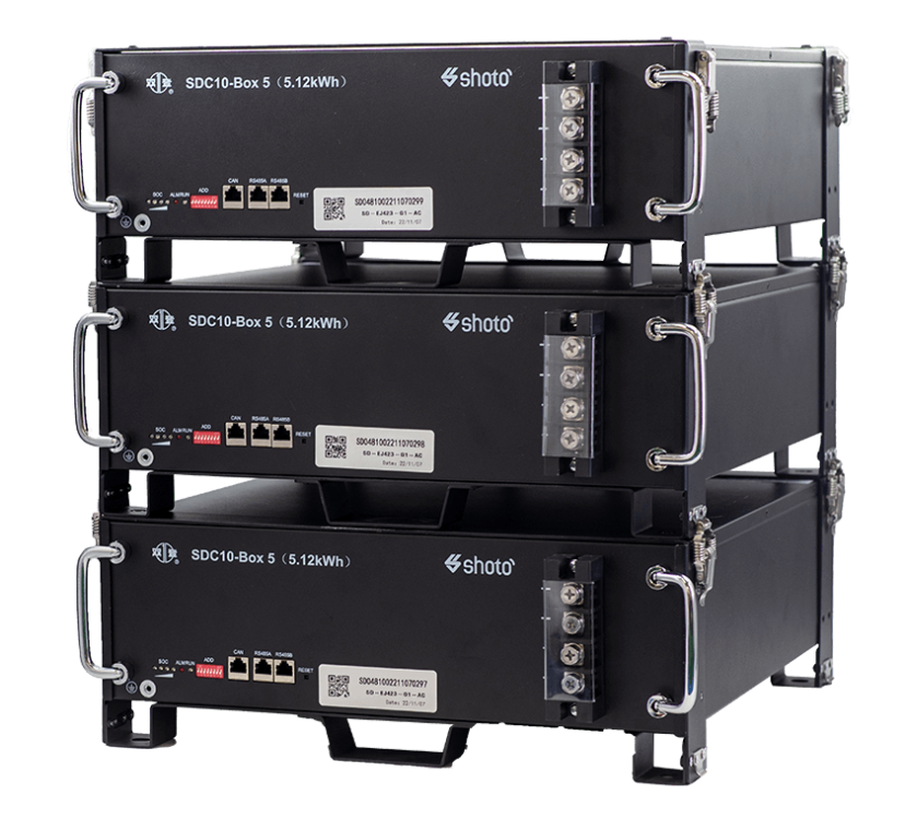
Or the SHOTO 10-Box 5 stacked and secured bit diffrent to rack mounting but maybe gives you better ventilation. Here is your battery in modular form 15kwh nice for scalability
-
Managed to get the info from my client, off grid, load disconnected Growatt SPF3000LMV 24 system configured to SBU. Asked him to dissconect load and immediately connect the load so the inverter fan can start up dissconect load and take the idle consumption with fan running. Consumption via Victron SmartShunt.

-
They have 5 units left but you will have to jump before they are sold. https://www.bobshop.co.za/bsl-battery-51-2v-125ah-canbus-6-4kwh/p/593512073?gad_source=1&gad_campaignid=21817487037&gclid=Cj0KCQiArt_JBhCTARIsADQZaykfxspJMkGU_rR9lylQ5wR3-wEpopPB4A-zBtoYYvLVkEVwsMsXi9YaAlx-EALw_wcB OR You add the BSL 135ah they are compatible Invert SolarBSL Battery 51.2V - 135Ah CANBUS (7kWh) Lithium Battery -...The BSL Battery 51.2V - 135Ah CANBUS (7kWh) is a high-capacity LiFePO4 battery ideal for solar and off-grid energy storage. It features integrated CANBUS communication for seamless monitoring and mana
-
Back to your original question. I have installed a Growatt SPF3000LMV 24 system with 450ah( 11.5kwh) battery capacity. It is monitored by Solar assistant and a Victron Smart shunt. Solar assistant is not accurate enough to measure idle consumption but the smart shunt is capable of measuring it very accurately. I will ask my client when it will be convenient to switch the output breaker off to measure idle consumption from the battery as his system is off grid. It would be interesting to see what it takes to keep this baby 👶 alive 😉 😀
-
@Piet de Pad @Denns True, the majority of buyers care more about capacity and PV ratings — agreed. But from a practical off-grid and backup perspective, idle draw has a direct effect on battery sizing and runtime. If an inverter idles at 60–75W, it consumes ~900Wh overnight. That's not trivial — it's 20–25% of a 5kWh battery’s usable energy. So while manufacturers rarely highlight it, idle consumption is definitely a meaningful spec for real-world performance. People underestimate idle consumption big time. We brag about 3kW output and 6kW surge, meanwhile the thing is quietly burning half a kilowatt-hour every night doing nothing. At 75W idle(realistic), you throw away almost 1kWh between sunset and sunrise — that’s a fifth of a 5kWh battery gone before you even turn on a light. So yes, it matters more than most think
-
Should you decide to parallel the 2 above-mentioned packs Ensure before you do the parallel connection that both batteries was charged individually to 100%Soc. Also check the terminal voltage before connecting in parallel and should not have more the 0.5v diffrence. Then pre- charge the inverter and connect the paralleled bank and charge both together to 100%Soc.


