TaliaB
Members
-
Joined
-
Last visited
Everything posted by TaliaB
-
Asked and answered by @hoohloc

-
What is your inverter rating? 16mm² Swa can carry 100A. Running Swa from your roof cavity would ge best if there is a conduit from the top that enters the flush mount db. Otherwise chase the wall and bring it in from the bottom. This is how it is normally done from your point of supply.
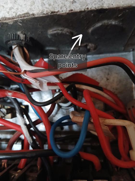
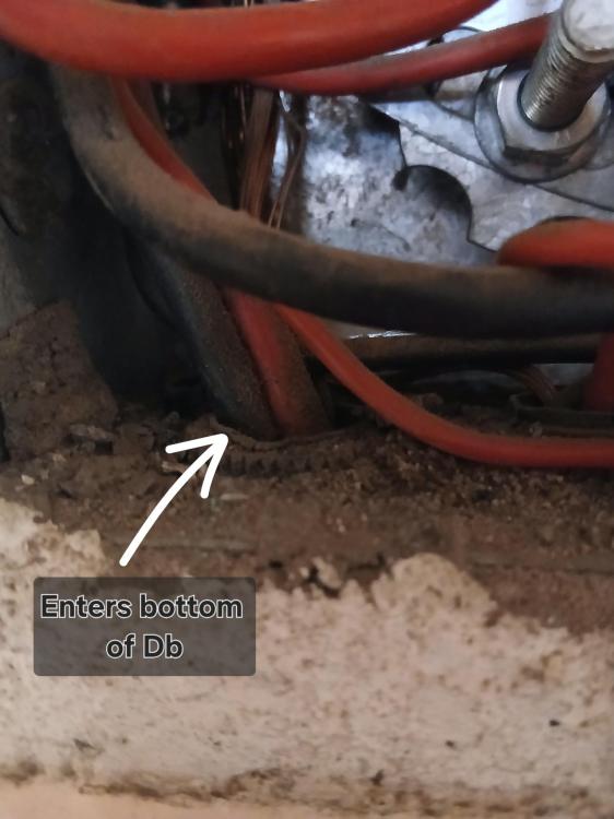
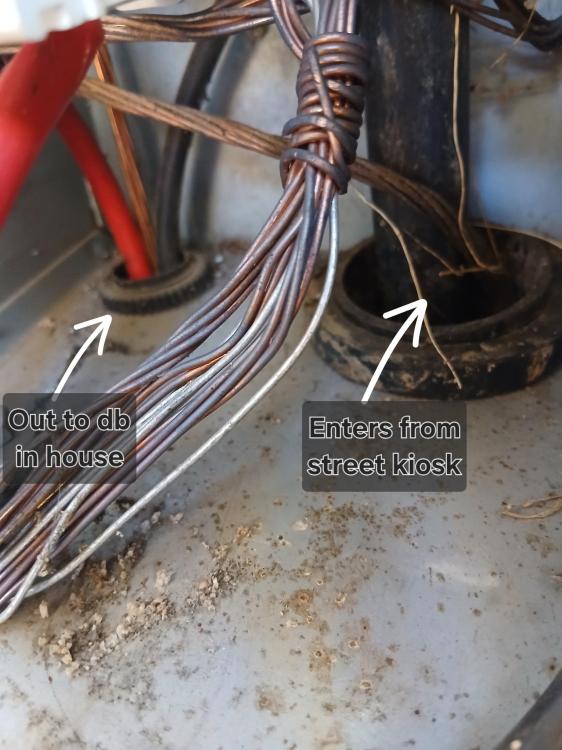
-
Why do you want to use SWA cable for inverter input/ output? They are extremely difficult to work with especially 16mm² 3 core. Is there a reason you not considering 10~16mm² Norsk cable?
-
First of all i would like to know from @Koch903 are the Sungrow inverter quoted 48v system or Hv battery system. If you are looking at the Sungrow SH10RS class it uses Hv batteries. Which battery module where you quoted on the SBR or SBH. The SBH is Sungrow’s newer higher performance platform where each module is 5kwh. The SBR modules are 3.2kwh. Hv inverters are more effiecient ( if Sungrow Hv) handles high loads much more gracefully than the 48v counterparts. I agree with @frivan Sungrow are definitely inverter system to consider.
-
Being part of a BESS installation in La Réunion island no stone is unturned regarding safety. A company called Akuo Energy was tasked with the building of Lfp battery rooms and enclosures.. Primary focus was on the prevention of a thermal runaway catastrophic event within Lfp battery enclosures. When thermal runaway starts propagating the first line of defence is the detection of Hydrogen gas. The failure progression happens in distinct stages, moving from silent chemical breakdown to catastrophic fire or explosion. The Pre-Runaway Phase (Off-gassing): As the cell heats up and reaches roughly 150 to 180 deg due to an internal short or abuse the solid electrolyte interphase (SEI) begins to degrade. This breakdown releases Volatile Organic Compounds (VOCs) and hydrogen gas before the full runaway sequence takes over. To mitigate full blown fire or explosion Hydrogen sensors are used that triggers flame explosion proof extractor fans and AOV's( automatic opening vents)to ensure the Hydrogen and air mixture does not reach critical levels. For us with small scale lfp installations your best friend would be well ventilated battery areas with moderate charge and discharge curves. Hydrogen sensors could be fitted as a early warning but that would be an expensive exercise. I will do the research and see what i can find in South Africa in the form of pure diatomic hydrogen gas warning systems.
-
Incident closer to home. In all of the information gathered on this post what is or was the root cause of the thermal runaway events? Take for instance the sealed container, what was the temprature of the battery packs inside the non ventilated container or was it ventilated?? In all of the videos the exact cause of LFP failure is not disclosed or diffucult to pinpoint. What is the failure rate of LFP 1 out of 40 million ? How to prevent thermal runaway in our domestic setups. Basically do not stress abuse or damage the cells apart from that nothing in life is certain misfortune lurkes in every corner of our lives in diffrent shapes and forms. All that we can do is to endeavor to be safe as humanly possible. FIRE OPS SAFIRE OPS SA - Batteries catch fire at Standard Bank offic...“Fire Ops teams were dispatched at approximately 09:00, where they encountered an intense blaze inside a container housing two 300kWh lithium-ion battery racks,” said Koekemoer. “Despite nearly two ho
-
Some important information about LFP thermal runaway from Battery University. https://www.batteryuniversity.com/article/bu-304a-safety-concerns-with-li-ion/
-
Sorry for the late reply to your question but please embed the link so it shows up as@TaliaB . The price is site specific eg panel distance from geyser roof tipe.....ect. Ballpark figure between 17~ 18.5k. This installation is a dedicated system change to your electrical installation and as such needs a Supplementary Certificate of Compliance (CoC) to cover the new work.
-
You might want to have a look at the Elon Smart system from Kwikot . Below link for the system setup. I have installed a few and the work great. 3 x 550w panels in series will work quite well.
-
Solis Hybrid Inverter 5KW S6-EH1P5K-L-PRO does support generator integration and effectively has a configurable GEN/Smart Port capability automatic generator start/stop, generator mode peak shaving, smart port functionality. So in your earlier kettle example: 2 kW inverter generator connected to the Solis: kettle drawing 2.8–3 kW if you have PV available and/or battery …the Solis can supplement the shortfall from: battery, PV, or both simultaneously. It behaves much closer to a Sunsynk/Deye hybrid than to a traditional off-grid inverter. The generator does not need to carry the full kettle load alone. The inverter can “assist” using DC-side energy. PV production during daytime reduces generator loading automatically. The only caveat same as with Sunsynk is that tiny inverter generators can sometimes have voltage sag, frequency drift or react slowly to sudden step loads if that happens, the Solis may disconnect from the generator input temporarily. Victron systems are still generally considered the benchmark for weak-generator handling through "Power Assist and ESS, but the newer Solis S6 hybrids are much more capable than older hybrids in this regard. SANS compliance for the generator installation itself still needs to be considered separately. Generator output -dedicated breaker/isolator - inverter GEN input. Proper earthing conductor from generator frame to the installation earth system. Neutral-earth bonding handled in only ONE active location at a time. As soon as utility power( Eskom is interrupted) the inverter will create the earth/neutral bond on output so no need to bond the generator as GEN input is not seen as utility input to the inverter input.
-
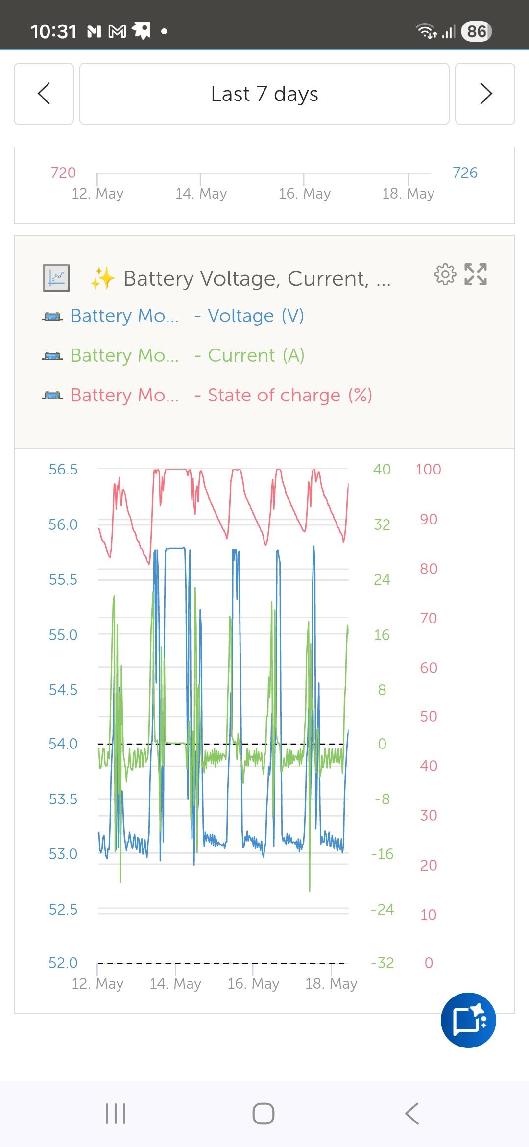
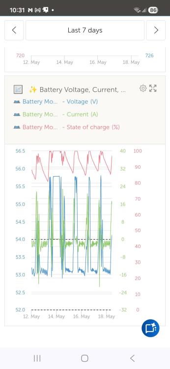
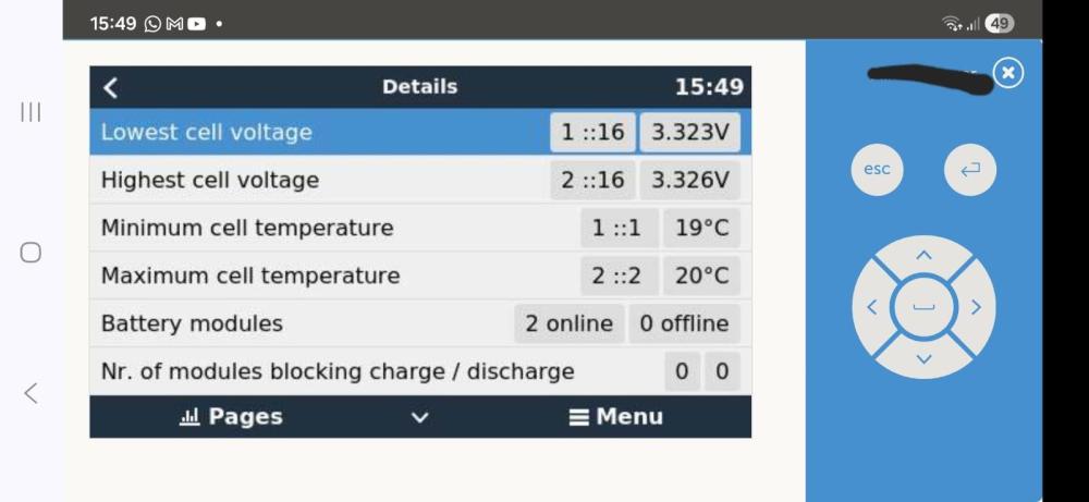
On VRM portal create a Widget to show you battery SOC vs Battery current vs Battery voltage. Also ensure your bms is communicating with the system. Then on VRM check under Battery details for the highest and lowest cell voltage.
-
You will have to upgrade your solar system, you have a 8kw inverter 40kwh battery capacity but you can only have 2760w of solar power available much less during winter. Your maximum yield in winter will be 12kwh if that spit between your loads and charging. So your load demand far outweigh your solar capacity.
-
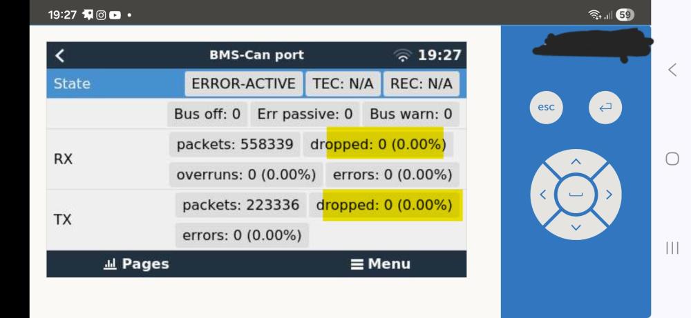
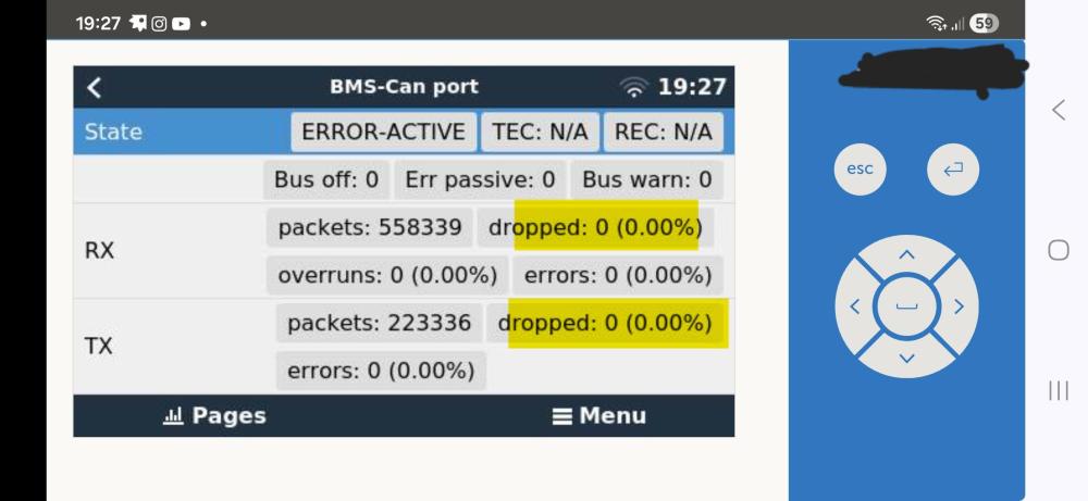
Yes I agree the 55.2v = 100% Soc. @jdido87 i will get the installer involved to get the batteries tested by the supplier. Insist on getting al 3 modules tested in parallel with communication enabled to ensure data packages are not dropped. Example of a healthy CAN network communication from a Victron System.
-
Yes, same principle applies. The trolley’s inverter has a maximum continuous output rating. Your Ellies unit is rated at 1440W, so when Eskom power is present and the trolley is switched on in bypass mode, the total load passing through it should still stay below ±1440W. The Navasolar 1kW trolley will likewise be limited to around 1000W continuous output/pass-through. If the load exceeds the inverter/bypass rating, the unit can overload, trip, or in some cases damage the internal transfer relay or inverter electronics. Always size the trolley according to the maximum load you intend running through it.
-
Switch OFF lithium/BMS communication and use “Lead Acid/User Defined”. Manually enter safe lithium voltages ONLY as a short test. If the battery immediately starts charging the problem is definitely BMS communications or permissions. This is one of the fastest ways to isolate the fault. Based on the symptoms, my suspicion order would now be battery BMS charge inhibit 1.CAN/RS485 comm issue after firmware update 2.Max charge current accidentally set to 0A 3.Corrupted TOU/force-charge state Less likely: actual PV issue The fact that PV instantly ramps when the pool pump starts is actually very good news the solar side itself appears healthy. Then Fully restart BOTH battery and inverter Not just the inverter. Proper sequence: Turn off PV isolator Turn off AC breaker/input Turn off inverter Turn off battery breaker/power Wait 5 minutes Then restart: Battery first Wait until battery fully boots Inverter second AC input PV last This often restores CAN/BMS comms.
-
If you can supply historical cell data, especially delta on the 2 packs and SOH i might have a client in Westville that would be interested. For me the Sunsynk battery modules was always overpriced new as seen in your link from Communica. I can purchase a FW 10/8 for 46k but for 2 x Sun Bat 10.65kwh at your price it will be a good buy depending on the balancing of the cells in both packs. Communica South AfricaSUN-BATT-10.65KWH-WMSunsynk SUN-BATT-10.65KWH-WM Batteries SUNSYNK Li-Ion Battery LFP Wall Mount 10.65Kwh 51.2VDC 208Ah, Charge Voltage:55.68~56.16vdc , Discharge Vltge:45.6~56.16vdc , Charge/discharge Current:100A 5000W
-
Is the system operating normally apart from the displayed Ah value? For example: • Does SOC drop normally? • How far have you discharged the batteries(state Soc cutoff) • Any low battery shutdowns? Sometimes Luxpower displays the wrong Ah value while the BMS SOC still works correctly.
-
Yes, it should technically work if the Solis firmware supports frequency-watt derating (frequency shifting / droop control) in island mode, and many people have AC-coupled Solis units to Victron systems successfully. But I would definitely verify the exact Solis model + firmware because some regional Solis firmware versions historically did not respond correctly to Victron frequency shifting. Also ensure the PV inverter sizing (factor 1 rule) is sensible relative to the 3 × 5kVA Multis and battery bank.
-
The Neutral IN shown in the diagram is there because the relay logic depends on the neutral reference during transfer/bypass operation, not merely for bonding the output neutral itself.
-
Below Relay configuration for Neutral/Earth bonding using utility(Eskom) to drive the relay coil. Use a 1 amp fuse on the live leg of the relay coil.

-
Not familiar with Macsell.store never bought from them. The Dyness lfp is good quality. Bought from Solar Warehouse professional service, staff has good technical training on items they sell and will go the extra mile to sort issues out. I can recommend them.They also sell the Dyness DL2.5 25.6v 100ah Lfp battery. See link below. Solar Warehouse SADyness 24V 100Ah 2.56Kw DL2.5 Lithium BatteryDyness 24V 100Ah 2.56Kw DL2.5 Lithium Battery Dyness DL2.5 is a good alternative for lead-acid batteries and a perfect match for on/off-grid applications in areas with limited or no grid access. It is
-
No you cannot just install a 300–350 kW hybrid inverter system behind a 200 kVA Eskom supply without formal approval and likely network upgrades. You mentioned: Supply: 200 kVA Proposed inverter: 300–350 kW (~300–350 kVA) Immediate problem: You are proposing generation larger than your point of supply that triggers Nersa registration required and Eskom connection study. Not a simple SSEG anymore moves into embedded generation project territory. In real projects like yours (irrigation / farms) Option A What most guys do (legal route) is upgrade supply to 500 kVA or MV then install 300–500 kW solar. Option B Hybrid workaround (semi-legal if approved) Keep 200 kVA supply and install large PV. Use zero export + strict control, but still requires Eskom approval. The second option if you don’t want to upgrade to 500 kVA Eskom supply you can go off grid(remove point of supply) and install what you want(need) with backed up supply in mind.
-
You ain't seen nothing yet 😂 You’re 100% right on one key point not everyone is solving the same problem. If your primary goal is resilience and independence from Eskom especially with cable theft, outages, and general instability then oversizing inverter and battery capacity is a completely rational decision. In that context, ROI isn’t just rands per kWh, it’s availability, reliability, and control, which are hard to price but very real. Where I’d challenge the approach slightly is on how that oversized system is then operated. Using batteries to deliberately dump energy into a geyser at 04:00 to “make space” sounds logical at first, but technically it’s still one of the least efficient energy paths. You’ve already paid a premium to store that energy in LiFePO⁴ you then cycle it (adding wear) only to convert it to heat which could have been done directly from PV the next day Even with “excess PV” in mind, most systems can be tuned to absorb surplus during the day instead: Raise geyser setpoints during solar hours (e.g. 70°C with good insulation) and use staged or priority-based load control (one geyser at a time) Shift workshop loads where possible into sunlight hours on weekends or flexible days. That way you avoid unnecessary battery cycling, preserve battery lifespan (which is a major capital component) and still maximise PV utilisation. On the “creating storage space” argument in a properly sized system, that situation should actually be rare. If you’re regularly hitting full batteries and clipping PV, that’s usually a sign the system could benefit more from additional daytime loads or even slightly less battery relative to PV Your use case (lathe, welder, evening workshop work) is actually one of the few legitimate reasons to have a larger battery bank because you genuinely need high-power energy after sunset. That’s very different from heating water, which is a low-grade, time-flexible load. Also, your ROI recovery (~27% in 1.5 years) is solid but I’d argue that’s largely driven by: 1.Tariff escalation 2.High self-consumption 3.Avoided downtime Not necessarily by how the batteries are being cycled overnight. So I think the middle ground is: Oversize for independence if that’s your goal absolutely valid. But once you’ve got that system, run it in a way that prioritises solar-first, battery-second, especially for thermal loads like geysers. Different goals, same physics and the physics still favours using the sun directly wherever you can. 😜
-
Your comments mixes a few practical truths with some assumptions that don’t always hold up technically or economically. I agree with the first part smallest battery that meets your actual use case usually gives the best ROI. Especially in grid-connected systems, batteries are often the most expensive kWh you’ll ever “buy,” so oversizing them for things like geysers or daytime loads doesn’t make much sense when you can rather push that load into solar hours. Where I differ is the jump from 10kWh to 20kWh being a “problem.” That’s more a system design and brand limitation than a universal truth. Many modern rack systems (Pylontech, Hubble, Dyness, Freedom Won, etc.) are inherently modular at ~5kWh per unit, so expansion is incremental by design. If someone installs a monolithic 10kWh battery, then yes they’ve locked themselves into larger expansion steps, but that’s a product choice, not a battery principle. On the second-hand argument: In theory, 5kWh units might be more liquid but in practice, the second-hand battery market is still very immature, and buyers are far more concerned about: ●Cycle count ●State of Health (SOH) ●Brand reputation and BMS compatibility A 10kWh unit with good telemetry and warranty traceability will often be easier to move than multiple smaller units of uncertain history. Also worth noting: more small batteries = more parallel strings, more comms complexity, more potential imbalance issues over time. There’s a real engineering trade-off there, especially in systems that already push multiple parallel packs. The “phone two friends” comment is funny, but practically speaking, installation logistics shouldn’t drive system design. Most 10kWh-class batteries are still manageable with proper handling, and installers deal with this daily. Get yourself one of these: For me the bigger picture is this: Size the battery for night load and outage requirements only use solar + load shifting for high-energy loads (geysers, pool pumps, etc.) Keep the system modular where possible, but not at the expense of unnecessary complexity. If anything, I’d argue the real optimisation is:.Spend on panels first, battery second especially if the grid is available. That’s where the real ROI difference sits.

-
To answer @MuneebK question 1 x 10.6kWh or 2 x 5.32kwh batteries? Installing 1 battery module makes more sense less wiring less components much simpler. As for the rest of the discussion my 2 cents. Try not to use high resistive loads(geysers) from your batteries. Let us compare two very different cost models: PV generation vs stored energy. Additional solar capacity (R/Wp) is still far cheaper per kWh produced over its lifetime than LiFePO⁴ storage (R/kWh usable). Using batteries to run a 2–3kW resistive load like a geyser is one of the least efficient uses of stored energy (high discharge rate + unnecessary cycling). If utility/grid is available, it generally makes no financial sense to size battery capacity for occasional cloudy periods just to support non-essential loads like water heating. That’s an expensive way to avoid a relatively cheap backup source(Eskom) used a few days a year. A better approach is load shifting + thermal storage: Heat the geyser during peak PV hours (10:00–15:00) and set thermostat to ~70 °C to increase stored energy capacity. Use a geyser blanket + pipe insulation to reduce standing losses. Let stored thermal energy carry evening demand (mixed down at the tap). This effectively turns the geyser into a low-cost energy storage system, avoiding battery cycling and preserving stored electrical energy for essential loads..Also consider load staggering only one geyser active at a time..Prioritise based on SOC or excess PV. Hierarchy should be: 1.Use PV directly 2.Shift loads to sun hours 3.Store as heat (geyser) 4.Use batteries for essentials 5.Use grid as fallback Oversizing batteries to run high-power thermal loads at night is usually a capital inefficiency, not a system optimisation.