


onobeka
Members
-
Joined
-
Last visited
Everything posted by onobeka
-
I have B2.0, B3.0.24 and B3.0.28. I will try the "config" command and report back.
-
Much more work probably means much longer work, that’s true. Yet, since lifepo4 cells are flat voltage curve energy storage, extreme ends are sensitive. I agree that leaving them to go 53.2V might solve my claimed issue in a few weeks/days, but what if it does not? Will I run them for a year in this behavior, where one cell (or few) are exposed daily to over 3.6V? That might be permanent damage.
-
Thank you. On this forum I've read that pylontech balancing starts at 3.45V, that's 51.75V. And anyway above that value there's not much capacity in Lifepo4 anyways, I thought to not stress the cells to much especially with the tendency of that cell to overshoot 3.6V. I have the same phenomena at 52.5V total voltage, so the balancing happens at that value anyway, and I guess there is no way to speed the balancing process by going higher voltage ...
-
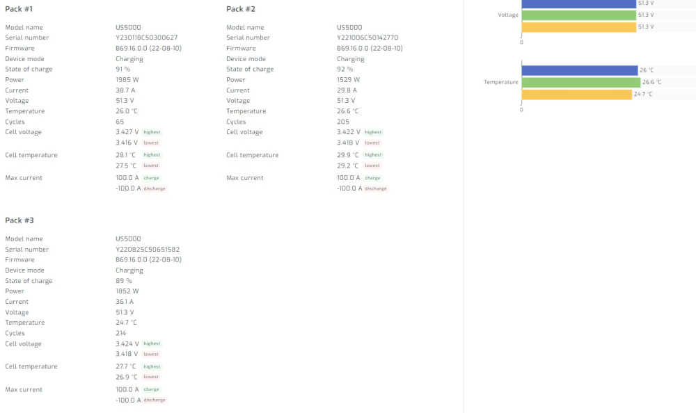
I have three us5000 connected in parallel. They were all purchased at different intervals, latest one was October 2023. They have the following cycle count: 65, 205, 214. I've ran them both in PYL mode (easun/voltronic at 53.2V) and user (52V float 52.5V bulk). I have an issue with the latest module. There are no alarms/no red led lights and nothing bad in the log files that I could download with BatteryView. Each day, once the voltage of the cells is above 3.45V (generally), there is a drift in between the highest voltage cell and the lowest voltage cell of about 0.14V. Highest would be 3.61V while the lowest would still be 3.47V. This happens gradually after 90% SOC. Below 3.4xV the cells show almost no imbalance. The other two modules have a cell imbalance of 0.02V generally and it's maintained, irrespective of SOC. Also the other two modules reach 100% faster than the 1st module, which stays at 98% for a while (20mins) in which the BMS temperature reaches 40C, while the cells remain at 27-28C(similar as the others). Then, the module would reach 100% as well and the cells would be 3.53-3.55V. I know it's the balancer that does it's thing, but this happens every day and 100% SOC is maintained for 4-5h. Pylontech support says to charge them individually to 53.2V OR to force charge them with the inverter and keep them at SOC for 5-8h. Well, the second option is done almost every single day in the past weeks. In the pictures below you can see the behavior in the reverse order (of the pictures). I am back to PYL mode to satisfy their requests of 53.2V. Before mid of last week I was running them at 52/52.5V in order to not have one cell go above 3.6V. Looking at individual cells with batteryview, it seems that it's not one cell that is too high or another too low, rather it's split in two groups. Please advise. The seller tells me that if Pylontech support will not say it's an issue or if there is no red led or alarm, they will not do anything about it.
.thumb.png.64303aebd5e30ebc9becfea73a2e32b4.png)
.thumb.png.39db7f09b590af0d881d657730c3054b.png)
.thumb.png.90c53ad825eb9aa1a1583cc89e52ab2a.png)
.thumb.png.529b5b2b62b6c7ad41ab988a1aea59ee.png)

-
Calvin, that is a lot of management that you do. I do not follow why you think they will overshoot in case not all batteries reach 100% nearly at the same time. In case one takes longer to get to that stage, it means it's in balancing mode, and needs to "burn" some current from one cell in order to make room for the another to raise the voltage. Hmm, but yes, maybe it will overshoot. On the matter, I've set the two inverters in parallel, using just set of breakers. They work well and I can stop/start an inverter on the fly even if that is the the master, the other would become master instantly. There is no downtime at the loads. Also, I've measured the AC out voltage before connecting the L wires together while the N wires were connected. The voltage difference observed between the two L wires was 2-3V. Thx @Coulomb.
-
Yes, that happened from day 1. I’ve added one new module to the bank every 3-4 months later, and always the new module became the master. But that’s the information us5000 communicates as well, that it should be charged to 53.3V. During a normal day it would reach 100% at lower voltage, even 51.5V from what I remember, stop charging but later in the day it would charge a bit more and eventually reach 53.3V. That is 3.55V per cell, not too dramatic. However I prefer lower. That’s why I went with voltage and 52V.5V bulk and 52V float. Sort of unrelated to the 53.3V thing, but even with the 52.5V setting, I do have a sort of an issue I believe with the newest module, after 92-95% one of the cells would imbalance to a difference of 0.120V: highest ca reach 3.6V, lowest would be 3.48V. The bms temperature will rise, meaning that the balancer is busy. The cell temperatures remain around 20C, while the BMS can reach 40C. The module will stay there for a while, at 98%, the other two modules will be already at 100%. After that while(can be one hour) the module will finally be at 100%, cells would be balanced and the voltage of each cell would be around 3.48V. No alarms, no records in the logging. Pylontech says it’s normal. I do not consider it to be very normal.
-
I have four chargers: - the Easun iGrid IV which works currently as inverter as well; 2 strings of 6 panels in parallel, 240V. - another Easun iGrid IV, which works currently only as an MPPT <- this one is the subject of the above conversation, to set it up also as inverter, to be able to stop the inverter side based on load; 2 strings or 5 panels in parallel, 180V. - one small Easun 80A mppt charger, 150V; 3 strings of 2 panels in parallel, 80V. - one Victron Smart Solar 250/60. 2 strings of 4 panels in parallel, 150V. They are all connected to DC custom busbars with fuses on the positive only side. They all are feeding 3xus5000 batteries, based on voltage settings. 52V float, 52V bulk and it works pretty well as the Pylontech BMS will limit the charging to 20A, above 90% SoC. I used to have BMS communication between the inverted and the Pylontech bank. I could still run it as such, but it used to take the batteries to 53.3V, to high in my opinion. I've limited the maximum charging current to the batteries either from the chargers or panels (you cannot limit the small Easun mppt). Current maximum, theoretical is 140A, which is below 0.5C of the 300A battery, but it rarely goes that high. Probably during summer months I will lower the maximum current as the days are longer. Also I am running two sets of Pylontech cables between the batteries and the busbar, so 50mmp.
-
Yes, I see it. Indeed, it looks that in the version you've shared they've put more thought into it.
-
Thanks Calvin, I did search for that manual and I've found this one, as 4KVA/5KVA Parallel Installation Guide: https://www.mppsolar.com/v3/catalogs/PIP-HS_MS Parallel Guide.pdf. Anyway, I am sure you know what you are talking about. I will probably try first the single breakers route (as it's simpler for me, I just need some 6mmp cables), but I will do the measurement Coulomb recommended before connecting the L wires in the breakers.
-
Thank you both for the clean and exhaustive answers. If this on the fly turn on/off does not work or not with my expected benefit, then the best option would be to have them running 247 time and take the hit of night consumption. Ok, now I need to decide if I want to run them in parallel or to split the loads into different phases, different AC-outs. There is the advantage of dynamically sharing the loads when one the the phases would be loaded more if the software is able to nicely achieve that. I am not looking for a perfect 50-50 split between the two units, rather a 40-60 would be acceptable as long as this does not go to 80-20. Distinct phases is similar to a triphasic inverter feeding loads hooked to each phase, which will never be equally balanced.
-
Thank you @Coulomb. I do not intend to change setting 28 (PAL) with my intended setup, rather leave them both on PAL (parallel mode) and turn off the rocker at the bottom of the inverter -> no AC out on one of them -> less battery consumption over night (I hope). Would this work? My plan was to use as said a relay to turn on off via a relay by means of an AC load measurement (tinyControl + clamp). Even if both inverters are set on PAL mode (single phase output), only one will be producing AC out 24h/7, the other would join the loads when necessary (>4kW load) and otherwise will work in MPPT mode (as today). Actually I am not sure that's entirely correct, except if there is no AC-in connected. Does it need to be connected on both paralleled inverters or just the 24-7 one? I guess if it's connected also on the secondary unit, it will never switch off during the night. There is also no need for it to run (loads less than 4kW so in theory it should never be turned ON during the night). OTOH if something fails with this control and I have AC-in on one unit only, it may trigger a fault (best case). I follow what you say with individual AC out breakers, to be able to check the voltage difference between the two and only then to feed the loads. But that's the only advantage of the two separated breakers, which can also be done if the Ns are connected together and the measurement is made on the output L connectors (without cables connected). Is it common that a difference of voltage is observed between two paralleled inverters?
-
Thank you! Maybe an additional question. As per manual, there should be just one AC-in and one AC-out breaker for the two inverters (in my case). The manual also states that the N line should be always connected, but that's the case anyway with a common breaker. Having two breakers has the advantage of being able to service one inverter while the other can be in service, but is there an issue of using just one set o breakers? I do not see one, but maybe there are. Better ask. Thank you!
-
Thanks Chris! What version of the inverter was it, if I may ask? Since these inverters choose themselves which one is master an slave, did you turn off the slave or regardless? Was there any downtime for the AC-out?
-
Nobody knows? I am looking for advice. Is setting units in parallel going to be a less reliable system? I read of a lot of issues, when setting up the connection, not so much about trouble later on. If splitting the loads on two distinct phases is possible, is this regarded as a more reliable path? Thx again! @Coulomb, any idea?
-
I do not want to start up a new topic. I have two units of the 5.6kW Easun round displays. So far I have been using only one in inverter mode, the other just MPPT mode (it turns off at night). I would like to set the two units in parallel, I already have the kit. For me it would be important to know if I can switch off the DC-AC part of one unit, while the other inverter would continue to work undisturbed without any impact on running loads. I did not find this in the manual, although the indication that the Master/Slave selection is ad-hoc and the fact that you can set the 28 setting by turning off the rocker (which in theory will not be simultaneous) and then restarting the units, gives me hope. The end goal is to be able to turn on one unit with a relay, in parallel with that rocker switch when the loads would exceed 4kW (for instance) and turn the unit off otherwise to save battery over night. The battery saving (self consumption) might not even be possible if the AC in is connected as well, as the unit will never turn off, unless I disconnect the AC-in breaker (for both). Since it's a bit of work, I thought I would ask first before trying or even worse before breaking something. I have the option to set the second inverter as a standalone inverter, next to the first, without the parallel kit and have different loads on each. Of course I cannot achieve my plan to turn one off when loads are low, yet if I cannot save energy with the previous approach, the only advantage of load sharing of a parallel kit is not that appealing to me anymore. However this approach would mean doubling the AC-in and AC-out breakers and SPD, compared to the above approach where the AC-in/AC-out are the same (currently hooked to the first inverter). Of course in both approaches they have their own fuses for PV and battery (like today). Thank you!
-
@Tinbum, @Nexuss, clear now! Thank you! I took another look into Tinbum's answer and I now see those values. One additional question, are those values read by using something like BatteryView or MultiSIBControl? I would like to see something like that for my batteries as well. I tried googling it (only shallowly) and nothing relevant came up. Maybe I need to take a deeper look. If you could point me in the right direction, I appreciate it!
-
@Nexuss Do you know that for sure for Pylontech? I mean that they have to be above 3.55V to start the balancing? Pylontech recommends charging between 52.5 and 53.5V, which would mean that their recommendation is not balancing in most situations.
-
Balancing of cells is an internal aspect. The reason I've connected them in parallel is to equalize SoC. I guess also that balancing is top balancing, so if there is current flowing from one battery to another while in parallel it means that one is charging (which is what happens), which also means that if the batteries are each close to 100%, there should be balancing going on, provided that the balancer is in it's balancing voltage range. I see no issue with having the batteries in parallel without an external charging source, this will happen at night with only solar charging or when the controller(s) are out of service for some reason. @Nexuss, "You are making the same mistake as in the Luxpower thread from the other day." <- where is the mistake in fact?
-
There are so many contradicting opinions on the Pylontech best practices that it's hard to pick one. I appreciate all opinions and I've tried this and that (probably most of the thigs I've read so far) and so far I cannot recommend somebody else what to do. I have little experience, only three units so far, added them gradually to my system. I had no issue with the first two. The third scared me a bit, seeing the BMS going to 48C on the first day with a cell at 3.64V and one at 3.4V ... now it's better, yet not flat balanced. 30mV imbalance is 0.008%. Not a big number, though.
-
@Kilowatt, sorry to hear that :(. Before going to voltage only, I was using the BMS communication to the inverter to manage the charging. The batteries got every day to 53.2 which is regarded as too high by the community. I've read on this forum that balancing happens at 3.48V (52.2V) which in case of us5000 is certainly not true, as I see a 30mV cell imbalance still after two weeks. I have 3xus5000. One battery is almost new (4cycles). I've charged it alone, and the other two, set them in parallel for 1h and then connected to the inverter. The new battery is set as master and when using BMS communication and the battery going to 53.2V, I can see that the BMS temperature of that battery is rising trying to balance the cells. I guess it's burning voltage of the higher cells while trying to charge the other(s). I can see that the higher voltage cell can reach 3.64V while the lower is trying to go above 3.5V. The cells in the other two modules are sitting at 3.54V. I went Pylontech for the sake of a solid BMS. I wish I didn't. Maybe the Voltronic (Easun) bus is overreading the voltage, and the battery is not actually at 52.2V but lower, hence balancing will not happen there.
-
@Coulomb, thank you! Indeed I have been reading about the premature float bug! After more observation and changing settings I can absolutely confirm that the batteries will not reach bulk voltage, only float. So, I’ve raised the float to 52.2V which is 3.48V per cell because I’ve read that is where the ballancer kicks in action, and from my observation it’s true. A little lower voltage and the unballanced battery does not raise the BMS temperature at all. Maybe there are other ways to check that the ballancer is working. I guess there are no firmware upgrades for my model or … I do not know where to look for them.
-
Yes, I would also reconsider having this experience, but it's too late now :). Yet, maybe my question was not well understood. Normally in the charging of the battery should first reach Bulk, stay there for a while and then get down to floating and maintaining of that voltage. However, in the case of my inverter, the battery only gets to to floating voltage and NEVER to Bulk. So, if I want equalization to take place, I need to set floating to 52.2V (3.48V per cell) and either set the Bulk to the same value or above. I think this is a bug of the inverter, not the pylontech batteries. I am in USE mode now (not PYL). So, even if the communication cable between the BMS and the inverter is there, the inverter does not use any values from the BMS, even the state of charge is wrong. The inverter thinks (based on voltage) that the battery is at 64% while the battery is fully charged.
-
That could be indeed the case. I've been running in user mode for 2days now and I did not get the behavior I was complaining about initially, no 51.2 setting either. I've set Bulk to 52V and Float to 51.5V. The batteries are not charging anymore above 96% and I think no balancing takes place either. Elsewhere on this thread I've read that the balancing of Pylontech happens above 3.48V. Also, my inverter stops charging at float voltage. I thought that first a battery will reach the Bulk voltage setting briefly and then float.
-
0V?
-
Check again your Back to Discharge Voltage setting, either in the inverter or in Solar Assistant. I am hunting an issue you can read about in here:
.png.7b70b0cc5480f6133ade773344c4afe0.png)
.png.7346b1c6521b8e62d58ff35af212bfc1.png)
.png.3ae572b9bfebf7aa6e9b820f78a3a25f.png)
.png.8056216fc73a2874d465573261812a15.png)


