Modina
Members
-
Joined
-
Last visited
Everything posted by Modina
-
@PsyWulf I don't read or follow any publications anymore. I have divorced myself from technical stuff. I refuse to listen to this post-Covid bullshit. What happened is that a lady I know in Cape Town still is battling with a roof repair before installing a new Victron system. On hearing that she is still not sorted, I mentioned that with the shitty weather we are having, any solar panels would anyway not produce anything meaningful. It's then that she forwarded me that link. I would not be worried about Chinese or Russian propaganda.... @Garthox I didn't even reach so far into the article or webpage, well noticed. 😅 However, it doesn't matter if this is the Fantasy and joke of someone. With the UN Chief Antonio Guterres saying that we are now in, I quote, "Global Boiling" the so-called real news is more fake than the most outlandish fantasy could ever be. I resign.
-
More laughable, fake, dis- and mis-information for a brainwashed, gullible world that will believe anything and everything that the MSM dishes up. This time about rain-drop power harvesting. You must be kidding me.... The below article was only published a few days ago. https://thedebrief.org/forget-solar-panels-here-come-rain-panels/ ...proof that the IQ of some people has evaporated into nothingness. BTW. This tech will work. It will produce some power for a small microprocessor project. The problem with this story is that the sheeple will think they can boil the kettle with it, if and when it rains. Even if it could, this is so dumb-ass stupid.
-
It is really no challenge to make a boost inverter that takes 4 or 5VDC and boosts it to 26V or even 56V. I mean, a typical taser will run from a rechargeable 3.7V and make 12KV or more. 😁 My first statement is not meant to mean that I suggest you build your own, but rather that your MPPT should have no problem boosting a voltage from say 4.5VAC to 26...27VDC required to charge a typical 24V lead-acid battery. I think your problem is likely to be found with that MPPT. I realise that wind generators do not have a huge selection of MPPTs available.... MidNite Solar seems to make some decent ones, but I think they are American and will likely cost a fair bit of money. An alternative would be to buy a buck/boost converter with voltage and current limit adjustment capability and then use that as your battery charger. You would also need to buy or make your own 3-phase full-wave rectifier but that is cheap and easy. The only downside is that this setup would not include a turbine brake system, for times that your battery might be full and high winds might cause the turbine to over-rev. For that you could use a over-voltage protection module which could switch a ballast resistor across the rectifier output at a certain pre-set voltage. My view is that wind generators are only for very specific applications. If you are really 100% off-grid in a very remote location. If you really know how to safe every last watt and you desperately need a backup to a solar panel system. I personally would first want to get this current system to work and get some experience with using it. See how much power you can get during a specific season. Upgrading can be considered at a later stage. There seem to be a lot of unhappy wind turbine owners that sit with systems that have been completely over-sold and fall far short of power expectations.
-
@Scorp007 Yes, agreed. But you get much cheaper battery under-voltage cut-out modules than the Victron. The following two are under R200 and don't need a multimeter to adjust, as they contain their own volt meter. https://www.robotics.org.za/XH-M609?search=battery protect https://www.robotics.org.za/YX-X0001-1 The real problem is that with todays L/S, people unknowingly discharge at X-Ah and then want to use a X/2.... X/10 Ah charger and then wonder why the battery can't cope. There is absolutely nothing wrong with using lead-acids if you have small loads such as a few LED lamps. But if you want to run a 80W TV plus auxiliaries for 2 to 4 hours, that's when things start getting problematic. As I have mentioned here in the past, I have a 24" HD-Ready LED Sinotec TV that can run straight from 12VDC and draws aprox 1A. Firstly one can save on the inverter cost, one doesn't sit with the inverter losses and at a power rating of less than 15W that TV will run for many hours from a 100Ah LA battery and still remain within the 50% SOC. Set-top boxes can normally also be run straight from a 12V battery or, to be on the safe side, connect a cheap buck/boost regulator. The only down side is that it requires some very basic DIY capability, to make cables and own a multimeter, so as to be able to adjust the output voltage of the regulator.
-
Note that I have no practical experience with wind turbines so accept the following as common sense opinions, some of which could be inaccurate. I am not sure what pickup device you are talking about. If the 3-phase generator uses permanent magnets there should not be any sensor or controller and the output voltage will likely be a linear function based on rotational speed. Permanent magnets cost money. I would expect an alternator to have lower production costs. Alternators use a field coil that needs to be excited, i.e. it needs power and that can be controlled if desired. I am in no position to make claims as to what sort of generators / alternators are used. I don't know the market, but I suspect that permanent magnet generators are likely. At least this is the impression I get from some youtube channels. I would expect the system to react immediately. You might be able to remove the blades and then drive the shaft with an electric drill for measurements and determine the output voltage curve. A dirty slipring on a new wind turbine. Mmm, that doesn't inspire confidence. 1.5 ohms is a substantial resistance. If you get this setup to work, it might be a good idea to apply some special-purpose grease as those sliprings will not see any action in some sectors, so self-cleaning will be limited. No. The regulator should contain a boost converter and it should start charging at substantially lower input voltage. I would expect charging to commence at 6 or 7VAC. At least for a 12V battery. It sounds as if that MPPT doesn't work properly. I know you said you have already replaced it.... If I was in your position I would do some basic tests on the turbine itself, as you appear to already have done. I would try to spin the turbine at different speeds and plot a basic transfer function of RPM versus output voltage. With the confidence that the turbine can actually generated a decent voltage, I would hope that it can produce power (i.e. an output voltage under load) and I would first set aside the turbine. I would then use a bench-top variable power supply - something like 0...30VDC at 1 or 2 amps should be fine, and test the MPPT charger. I would connect the PSU to two randomly selected input phases. Your charger will have a 3-phase rectifier at the input, so it will be safe to connect a DC voltage with any polarity to any of the phases. With a 12V SLA battery connected on the output of the charger, I would expect charging with an input DC voltage of no more than about 8 to 9V. Then experiment by increasing the input voltage. Note that depending on the voltage, battery SOC, etc. your bench-top power supply could/will run out of current and drop it's output voltage. So a PSU that can output many amps would make for easier testing, but even with only 1 or 2 amps you should be able to confirm basic working of your charger. If you don't have a bench-top power supply, see if you can borrow one or maybe buy a supply 2nd hand on ebay or whatever.
-
This makes little sense. Why 3x routers? And why do you power 2x DSTV decoders if you only power one TV. The first rule in L/S is to reduce your power consumption by as much as you can, especially if using lead-acids. Your Telefunken TV is an old LCD. LCD, by definition, uses cold cathode fluorescent tube backlight technology. New TVs use LED backlighting. LED TVs consume approx. 50% less power. Considering how super cheap a new TV is (in comparison to batteries) it would be a wise choice to replace your primary TV. You have a 120Ah battery. Even if the battery is only discharged to 50% SOC, that would mean you would need to replenish 60Ah. That intelligent charger seems to be a PSA008 - it can charge at a maximum of 8A. So it would take 60Ah / 8A = 7.5 hours. recharge time. In reality it is even worse because the battery has losses (converted into heat). You need to put more than 10Ah in if you want to draw 10Ah.
-
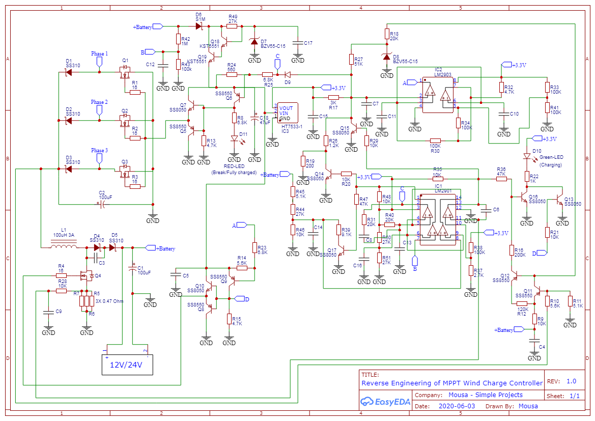
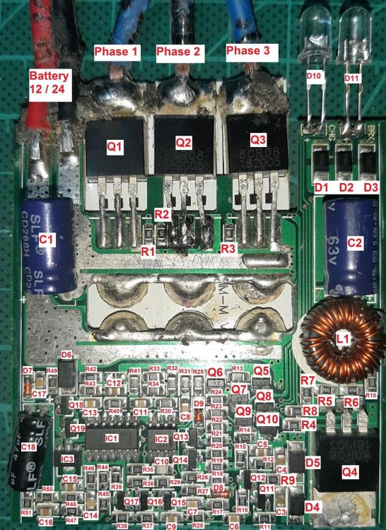
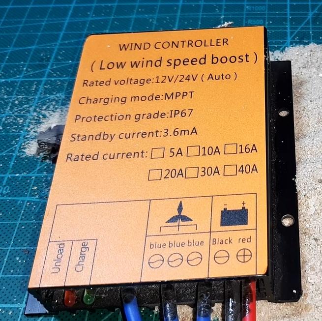
No, these are different. It has a extra LED (brake LED) It might be from the same manufacturer. A newer model. For the one I have posted, I have a back-engineered circuit diagram. I have downloaded it some months ago but cannot remember the source. I think it was a Youtube video with a link to the schematic. It is referred to as a MPPT charger but it has no microprocessor. It only contains a quad op-amp and a dual comparator with many bipolar and four MOSFET transistors. Because it has no processor and not even preset potentiometers, I can only conclude that it is dedicated for lead-acid batteries. Your MPPT seems to be made for Lithium batteries. Judging by the very similar physical appearance, I suspect that it might still based on the same circuit, but with modifications for the charge voltage and some other tweaks. Yes. Small wind generators do seem to normally have a boost-converter topology. And yes, it is possible to auto-detect your battery and adjust accordingly. After all, many PWM Solar Charge controllers are also rated for dual 12/24V operation. I first thought that your battery(s) might be Lithium (you didn't say what chemistry) and that the slightly higher voltage might be detected as a battery "full" condition by the charger. Seeing that your charger is for, or at least supports LifePO4 batteries, that theory doesn't hold water. You say there is no AC current. I presume you measured in-line with one of the generator phases? I would expect the AC to be loaded, i.e. an AC current flowing, even when no DC current is flowing into the battery. This would likely be under the following conditions: (1) battery voltage high (fully charged, and (2) AC voltage is over a certain threshold. The reason that you measured zero current could be that the AC voltage was not high enough. You will most likely not be able to read schematics, but I will attach the one for the other controller for the benefit of others on this forum. Note that this is a back-engineered schematic and it is quite a complex analog circuit, so there could be some errors. One would be able to connect a bench-top variable power supply to any 2 of the 3 input phases. Then slowly increase the DC input voltage and monitor what the input/output current/voltage is doing. For such a test I would first connect a small 12V lead-acid battery. Then maybe repeat the test with a 24V battery.

-
What MPPT are you using? Is it maybe the one below? There is not much info on this, but it seems to be quite popular for low cost systems.
-
There is a new pink collapsible rubber traveling kettle available. I would not consider it high quality but certainly low power. I wish it was made from stainless steel or glass. Pink silicone should rather be used for different toys..... It is mains operated, rated at 600W but was measured as 720W by Bigclive who reports that it will boil 500ml in about 5 minutes. R484 at Takealot https://www.takealot.com/portable-silicone-collapsible-travel-electric-kettle-pink/PLID73071560 Bigclive test https://www.youtube.com/watch?v=_6iDNP3QPxc
-
You only tested to about 51 degC. I presume that the PTC is still rather linear at these low temperatures. As a PTC is an engineered material with special, purposefully engineered characteristics. I presume it is made with an exponential transfer function at temperatures over 55 or 60 degC, so that it can self-regulate, if the blurb is to be believed. So congratulations, you have just prooven Einstein wrong. You have shown that all that we ever have learned in school and varsity is a lot of fake crap and that we should not "follow" or "believe" in the so-called science. Especially not the post-Covid science (!) So let me get back to the 24/7 movie I have been watching - Life in the 21st Century.
-
The conventional element is resistive. It will change it's resistance (slightly) as the temperature changes but this is linear. So you can measure the current drawn every 4 minutes and then calculate the average current consumption over the total measuring period. No problem. The PTC is designed to change it's resistance more, but what is important is that this is non-linear. If you take a current measurement every 4 minutes, you cannot simply work with the mathematical average. Instead, you would need to integrate the value over time. One day, when the Cabal/Elite will allow us to speak to the aliens and learn from their wisdom, we will make a quantum leap of science knowledge and learn the secret of traveling faster than the-speed-of-light, unlimited energy, etc. Until then, we are still ruled by the various scientific rules as laid down by Newton, Faraday, Einstein and others. In this case Einstein: The conservation of energy - Energy cannot be created or destroyed.
-
I have no problem with home automation as long as it is not connected to cloud servers, In fact, I personally would not even leave it connected to the internet 24/7 and only enable the connection for certain periods. The story below broke a few days ago and numerous channels have reported on it. It concerns Amazon accusing a customer of racism and purposefully shutting down the entire smart home. PS. I prefer not using and not sharing Youtube links. I prefer Odysee, Bitchute and Rumble, but I could not find this Louis Rossmann link on the other channels. https://www.youtube.com/watch?v=NfiIXooD77s
-
(Thermal) fuses are rated for voltage and current and can be used for AC and DC. By convention, a fuse is normally connected in series with the positive line in DC circuits and with Live in AC circuits. In practise it will work equally well connected in series with L or N, but for shock hazard safety, I would strongly recommend to keep to convention. No, don't use car fuses. They are not rated for such high voltages. Use a 20mm or 32mm glass-envelop fuse. You get various type of fuse holders for these. Any electrical wholesaler or a good hardware store should keep them. For your application I would keep the fuse out of sight and out of reach of your tenants. This is to prevent the McGuyvers of the world from creating their own fix with tin-foil or other crap, or even to bypass the fuse all together.
-
MCBs have two trip mechanisms. One magnetic and one thermal. The magnetic one is instantaneous (well as fast as a mechanical contraption can be) and it will act on a massive over-current. The thermal trip is intended for loads that are slightly over the rating. This could take up to a few minutes to trip, depending on how far over the limit the current goes. Being an electro-mechanical assembly there are tolerances and even the ambient temperature will have an bearing on how long it would take to trip thermally. You do not want a 5A MCB to trip at 5.5A or even at 7A. This would trigger nuisance trips due to in-rush currents.
-
Correct, but actually much worse. CBs have B- C- D- curve ratings. As far as I know domestic CBs in SA are all C-curve (correct me if I am wrong). A C-curve rated CB will only trip at 5 to 10 times the rated current. See here: https://www.se.com/au/en/faqs/FA290880/ Here is what you do - an expanded idea based on @Scorp007 fuse idea. You provide TWO standard outlets EACH being fitted with a 2A fuse. You tell your visitors NOT to plug in anything more than 300W. Obviously many will not listen and blow one fuse. They then have a second plug that still works. If they still don't get the message and blow the 2nd fuse, then they deserve to sit in the dark. This way you don't need to come out to your BB every time it trips as there is a backup. Once your visitors have left, you just check if both fuses are still OK.
-
I don't know what the guys that make such claims smoke. I think someone changed the definition of efficiency while I was not looking. But this wouldn't be surprising, because most words have their historic meaning changed by exactly 180 degrees, or like German Foreign Affairs Minister Baerbock would say, 360 degrees. 🙄 An electric heater is the only thing that has nearly 100% efficiency. As measured with the standard meaning of efficiency. In other words all energy you put in, is converted into heat. Depending how hot, a very tiny amount could be changed to light, mainly infrared. I have no personal experience with these, but yes, PTC elements are very good. The best part is that they are self regulating. They will go high impedance at a certain designed for temperature as to practically pass no meaningful current. It still would need a thermostat of sorts, to allow the end-user to down turn his hot water temperature and not always have to run the system at the PTC designed set-point.
-
Thanks @JustinSchoeman for that list. Interesting to see all the various manufacturers and also interesting to see that Victron isn't even on the list. Yes I know that Victron lost some sort of US certification and are hard at work rectifying the situation. I do NOT believe these figures. Go and laugh. Here is why. Those figures are WEIGHTED efficiencies. Weighted efficiencies are done at various loads such as 10, 20, 30.... 100% and then weights attached and the mathematical average taken. This means that the weighted efficiency is LOWER than the Max or peak efficiency that is normally quoted. Different organisations might apply different weights and this should be specified. There should be a definition for an A-weight, B-weight, etc. A certain weight might be used for solar systems in a certain climatic region. A different weight in a different climatic region. For a typical home user, yet a different weight, and so on. The fact remains that a weighted efficiency is less, possibly far less than the maximum efficiency. So, if someone tells me the weighted efficiency of an inverter is as much as 99% then I would suggest them telling it to the ferries. I would have to assume that the peak efficiency is then over 100%..... Not even a 20KVA toroidal transformer reaches 99% efficiency - at least what I could gather from a quick google search.... This is typical post-Covid crap coming from California. The whole place is spike-protein damaged. If this is MODERN Science, then it should be used for toilet paper.
-
Over 95% ? I simply don't buy that. Properly designed inverters will be typically 90 to 93%. It will most likely need very exotic components to reach 95% I didn't imply using 150VDC on a standard geyser. As far as I am concerned, electro-mechanical thermostats should be banned. One can never fine adjust those things. They are just terrible. One should still have some sort of intelligent control for the 150VDC and best would be to switch with a semiconductor based switch, such as a MOSFET.
-
I am a very big fan of low voltage DC. I define low voltage as anything less than 50V nominal. I think all small power consumers under 100W or 150W should be run from DC. The world is also slowly moving into that direction. The USB3 specification goes up to 5A 48V - that is 240W. However, for high power appliances needing a few hundred watts or more, DC doesn't make much sense. Another thing to consider is that the overall inverter efficiency is not very good at small loads. With zero load, your inverter has 0% efficiency. Best efficiency is normally attained at around 70 - 80 % of rated power, but this can vary depending on the design. For people that do not have an inverter, using 2 or 3 solar panels dedicate to geyser heating, then running a geyser at 140 - 150VDC would also make a lot of sense to me.
-
You have a very strange pre-paid meter !! My student tenants run out of pre-paid nearly once a month. 🙄 Never a problem recharging the meter when that occures. Most meters have the keypad and LCD display on the meter-box itself and are obviously hard-wired. However you get meters where the keypad and LCD is in a hand-held unit that communicates via an RF link , I think 433MHz, to the actual metering device. I have one of those. The hand-held unit is battery operated and the battery needs to be replaced on occasion, but I can't remember if I ever have, they seem to run for years.
-
MCB is rated for 250VDC. Is your solar string voltage below 250?
-
Well, at least with the Victron charger, you could switch to Lithium batteries at a later stage. The small-form-factor Victron chargers are IP65. That is a good and a bad thing. They are waterproof which might be handy for something living close to a gate motor? But IP65 means Victron embedded the electronics is some potting or rubber compound making this charger unserviceable if ever something would go wrong.
-
If your 80Ah battery is far away from the gate motor, then you can run a thin cable and leave the small 7..2Ah SLA in place. Your small SLA will then act as a short term reservoir (nearly like a capacitor) to handle the high current for the motor. If the large battery is close by (not further than about 2m), then remove the small battery and use relatively thick cable (2.5mm2 house wire should be OK). Your smart charger might apply high voltage pulses a fair bit higher than the typical 13.85V float charger output. It might be best to remove the internal charger, but I think it should be OK with it connected. (There are a number of different circuits used to implement a float charger, so one can't say for sure.) A smart battery charger is normally intended for occasional car battery charging. In this application it will progress through it's charging algorithm and at some point consider the charging as complete and then just maintain float charging. It often requires a complete reset to re-initiate a new charging process. This means the 230VAC as well as the battery would need to be disconnected. In your application you will not disconnect the charger from the battery. You cannot assume with 100% certainty that once the mains is restored, the battery charger is reset and will automatically go into a new charging cycle. This depends on the charger. It might, or might not happen. The only way to know is to test it. I would not trust the user manual to inform you, as much of these are written in Chinglish and are really superficial. In case your smart charger needs a proper power reset, you could implement that with a mains-powered relay. You could wire it in such a way that when the mains drops, the relay also drops out and disconnects the battery. HOWEVER, often these chargers have a high/low charge rate settings. The default is always the low current setting and needs to be manually overridden every time, after a reset... So it might be a good idea to buy a smart charger with only a single charge current setting. The above is applicable for typical 12V lead acid chargers you buy at Midas or Takealot. Otherwise you would need to spend more and get a Victron which should not have any of the above issues.
-
Thanks @Flouw. I had a look at various user manuals. A lot of them (including Mecer) do not have that setting, but I found one Mecer model that indeed has it. Good to know.
-
Well, then when does it make the noise? Only at power pass-through? The Multiplus-I uses two toroidal transformers and the Multiplus-II apparently only one. The transformer is used as the voltage step-up device in these so-called low frequency inverters. I think it is also used as a step-down transformer for battery charging. If it is silent during inverting, it means that it is not the transformer, but some other choke or inductor. Possibly the mains input filter that will be a rather large common-mode inductor. I am not sure how Victron mounts these massively heavy transformers. Smaller Toroidal transformers are normally clamped between two metal disks with large rubber washers. Tightening the single bolt through the centre would tighten the rubber clamp and could reduce the resonance. However, toroidal transformers have many layers of isolation tape between the various windings and the outer winding is also taped shut. So it is unlikely to be the transformer. Noise, be it low frequency hum or high frequency noise, is always generated by magnetic components - chokes, inductors and transformers. Irrespective of inverter type and manufacturer, I have seen a lot of bare enamel copper wire without any coating. These components should at least be bound with tape or some form of silicon, rubber, glue, epoxy or lacquer to prevent the windings from vibrating. One could use neutral curing silicon on these components, but this would not go down well if the inverter has a problem and needs to go back to the agent for under-warranty repair. It is very disappointing to hear that the expensive Mercedes of inverters, is allowed to pass QA and be vocal once it is asked to perform it's duty.... Even very small power devices can sometimes make a racket. I have a bathroom LED fitting that sometimes causes a rather loud buzz on the thin gauge metal base plate. It's not always the large, high power components.