Youda
Members
-
Joined
-
Last visited
Everything posted by Youda
-
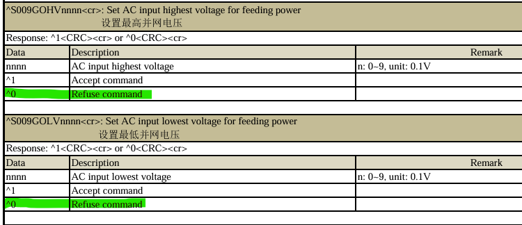
I believe the same, that is exactly how it generally works. But there will be at least two places with limits: first is the selected table of grid codes and their parameters, here reported via ZZ parameter. second would be the minimum enforced by the firmware itself. Reason: with my inverter, I can select grid code via GUI, and this changes the min voltage value. Apart from that, I can override min voltage value manually. But cannot go under 175V anyway. So, there's a secondary check. BTW: all these checks work even if you talk to inverter via serial protocol. Once you sent command with values that are out of range it returns an error and the command is not accepted:
-
Of course! Let me be a bit more precise: It's clear that keeping grid relay closed all the times, especially before the startup, would blow-up everything. The idea is: let the inverter to phase itself to the grid and close the relay first. Then, keep that relay closed forcibly during those valleys of grid voltage drops. I can imagine that the conditions for closing and opening grid relay are even more complicated and all the steps are being done in a predefined sequences, with check-ups before moving on. So, if the inverter detects a voltage drop, but is unable to open the relay, it will not proceed with de-syncing from the grid and changing it's own output voltage & frequency. But it will work for a second and then throw an error instead. But you're right, it's a dangerous test and if inverters in your country are pricey and hard to find (based on the amount of work you've put into fixing blown one) then it does not makes sense to undertake such a risk.
-
Just checked my Infinisolar hybrid, where I can specify the min.grid voltage before the disconnect manually, and the lowest value that Infini accepts in that field is 175V too. Based on that and since my Infini is from Voltronic too, I would say that all their machines use the same constants & limits for this....therefore, the constant 175 should be visible in the Axpert Max firmware on a couple of places: Either in a definition table, with all other limits, that are being referenced dynamically or as a true constant, embedded directly in the code-block containing the respective conditions for grid relay control. Finding the decimal value 175 and checking whether it is on the place that makes sense should be feasible - what do you think @kuba.cz and @Coulomb ? Well, I can imagine that there is another check that triggers something like "grid voltage too low error" once the grid voltage goes even more down. And the constant for the potential secondary check is yet unknown...but that can be diagnosed later.
-
Hmmm. What would happen if you keep grid relay forcibly closed during the drop under 175V? Maybe if will work. Maybe it will produce kind of "relay stuck error" Or, maybe it will burn....and you will finally have a reason to find and buy a better inverter ;)
-
Another option, when fusing only the positive pole of each series, is to connect negative poles and run just one negative wire further down. For your case, it would be 4 separate positive wires + 2 negative wires.
-
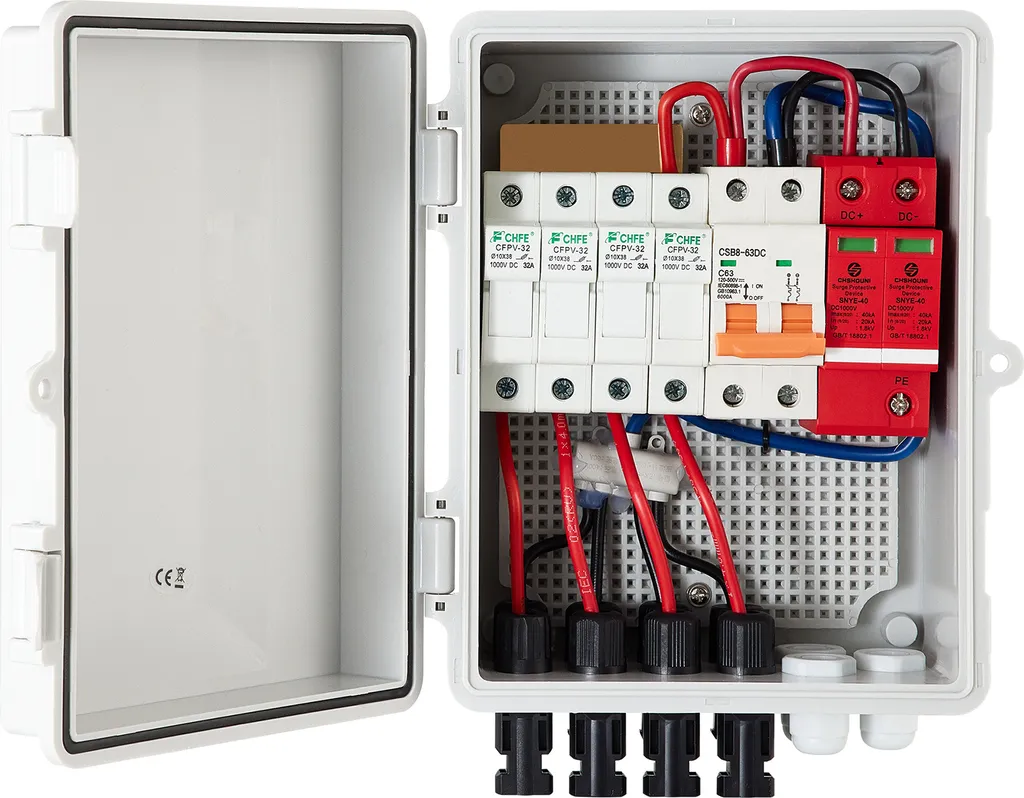
Normally, they use "pv combiner box" for this. Located near the panels, loaded with fuses. It combines the strings, allowing you to run just one pair of thick cables plus grounding to run further down. Has pros but cons too... Example:

-
This is better, but IMHO there's still a couple of space for improvements: Those 25A fuses might blow from time to time, since you have 26A (2x 13.9A) on each fuse. Each series of panels should have it's own fuse. AFAIK, paralleling two strings and then fusing both of them together, and then paralleling all of this again is not a recommended solution. Looking at components you have, I would suggest rewiring like this: String1 2 panels i series 1x 20A fuse String2 2 panels i series 1x 20A fuse String3 2 panels i series 1x 20A fuse String4 2 panels i series 1x 20A fuse Combine string1+string2 in parallel, go thru 2-pole disconnect A. Combine string3+string4 in parallel, go thru 2-pole disconnect B. Combine outputs from disconnect A + disconnect B in parallel, put into Surge Arrestor. Connect output from Surge Arrestor directly to the inverter MPPT input (no need for disconnect between the Surge Arrestor and MPPT input). But let's wait what more experienced engineers will say....
-
OMG, 4 new panels thru a single 6mm2 cable? How much amps is that - 60A? MC4 connector are rated for 30A. Are they hot and melting already or still nice and cool? Based on the length of cable, there will be some voltage drop. For example, 60Amps over 20m of 6mm2 cable loop is a drop of almost 4Volts. That is 240W of loss which goes in the heat. By rewiring you can make a bit more energy, but only during peak hours. In the low-light (low amps) the yield will be the same. But the most important would be safety improvement. BTW: there should be DC fuses whenever you parallel more than 2 strings together. Amp rating of the fuse should be higher than Isc, but lower than 2x Isc. Reason is: if one of the paralleled strings will be shorted, other 3 strings will start pushing Isc into it....and this might start a fire. With the proper fuses, the fuse will blow immediatelly.
-
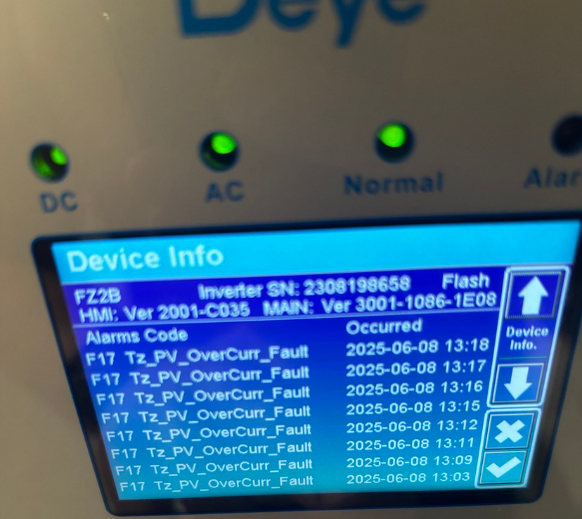
FYI, this is what Deye inverter does if the panels are able to supply higher current than Deye's MPPT Imp-max. When the AC load is minimal and the battery is full, then there is no problem. But once you switch-on a higher load, it causes PV current spike and Deye throws this error (instead of trying to limit the current). => not a good idea to connect PV modules that can go over Deye's Imp-max.
-
@bobah1248 BTW, is this service manual aplicable to your inverters? Axpert MAX E 11K TWIN service manual 20220406.pdf
-
Just one note to add: the root cause of why there is no 220V on the grid during the day is that other people are drawing too much current from the grid and the power line to the utility transformer is too long and thin. This causes voltage drop due to line resistance. The fact that ppl are using voltage stabilisers makes this even worse, as the stabiliser is just pulling even higher current from the line, in order to make a proper voltage (technically being auto-transformer with a servo). The propper fix is: to improve quality of the cable between you and the transformer, or make it shorter, or getting your own powerline from the same transformer. ...but I am sure that none of the above are manageable...
-
Input ADC yes Output ADC yes HVBUS ADC no I doubt that there will be fixed voltage ratio of HVBUS to Output that is checked. IMHO, these inverters just measure the output and then loopback. Since the output voltage depends on the loads too, loopback and PWM duty cycle will be used to adjust voltage on the fly. Shifting about 10V down should be feasible. Most of the times, there's a relay between output of the inverter and the grid. Inverter matches the grid frequency and phase by shifting PWM timing. Then it matches the voltage by altering duty cycle. Finaly, when all of this is matched, it closes the relay. The above is nicely visible on a dual-channel scope. For the export of active power to happen, inverter increases its output voltage a few volts above the grid voltage, while keeping the phase and frequency locked. This forces the energy to flow back to the grid. PS: On top of that, proper hybrids have an option to change phase angle between the current and voltage, which results in injection of some amount of apparent power to the grid. Sometimes, grid operators demands this function to be available via remote control of large PV installations, as they use it for grid compensation.
-
Deye is known to throw "Fxx overcurrent" error once the PV current goes above MPPT max limit. Way before you hit max Isc limit. Then it restars and after a couple of minutes you will see that same error again. If you will use inverter just for charging the batteries and powering loads, you can avoid most of the errors via limiting max charging current. If you will use inverter for exporting energy back to the grid, you will face these troubles a lot. While it will not blow up, it's not a good idea to run a device outside manufacturer-specified boundaries. Therefore, I would go for a model with a stronger MPPT or use panels with a lower Imp & Isc.
-
About the cooling issue and 80% vs 50% power-throttle: Thermal derating is normal, of course. Difference between the inverters might be caused by: location of the internal temperature sensors heatsink and thermal paste if both inverters are paralleled, the firmware may decide to load master inverter more than slave one. Aalthough 80 vs 50 percent is too much I'd say. Adding a water cooling sounds like a nice DYI project, but keep in mind that there's high DC voltage inside the box. One drop of water and box is done...and the operator might be done too. In reality, water cooling just transfers heat to some other place, where the heat must be extracted from water before it is cycled back. The only cooling medium with virtually unlimited capacity is the ambient air. Therefore, if you don't have a river or swimming pool in your backyard, you will need a secondary heat exchanger and air-blower that will cool the water. Even if you plan to heat 1000L of water for showering, you will need an extra cooling loop that will take over once that 1000L becomes too hot to be used as coolant. If you think about all the water cooling details and gotchas, it's actually much easier to fix the air ventilation. Just blow ton of ambient air directly to the inverter from bellow, collect hot air in the top and blow it out. BTW: some of the Axperts were designed in a way that air was sucked from the top and blowed down below. That's a stupid design, because normally the air at the ceiling is way hotter than air at the floor level.
-
Greetings to Tashkent! First of all, original Voltronic MAX E 11K is the off-grid inverter, with just a minimal grid-interaction capabilities: https://voltronicpower.com/en-US/product/detail/axpert-max-e-twin-11kw It can export some energy to the grid, but it's just a side-effect. Well, it is possible that your clones were altered by the manufacturer in a way that allows them some degree of export control but it will never be the same like having a purpose-designed machine. Using a proper hybrid inverter would give you more options to adjust export parameters. Speaking of Voltronic, their hybrid line is InfiniSolar PLUS, another brand worth looking is Deye. IMHO, Deye should be able to answer some of your questions about operational voltage range for the grid export, as they have working customer support. Anyway, the 170V minimum, when the inverter stops feeding into the grid, is dictated by so called grid standards aka grid codes. Every country is using one of these standards to manage their grids. And when comissioning an inverter, installer has to pick a proper national grid code from the configuration menu in order to be compliant. Most of the hybrid inverters have manual overrides too, but you can't go too much low anyway as firmware is imposing limits. Examples from a hybrid inverter: So, the proper solution to the export problem would be to find and use a hybrid inverter with a suitable manual override range This will work, normally there is an AD converter with a voltage divider sensing the line voltage. Altering this divider you simply "decalibrate" voltage measurements. One of the side-effects will be incorrect power reporting, as the power is being calculated on the fly, via reading voltage and current. But that's not a big issue. There is no silver bullet. A) Cheap but complicated: Technically, all the grid-codes and limits are being stored in the inverters firmware. Just find someone who is able to decompile, analyze and patch a firmware for you and you are done :D B) Propper but expensive: Get a better hybrid inverter(s). C) Smart but not cheap: Emulate a small hydro power. Use a spinning generator coupled with a motor, simple gearbox and electronic rpm regulator. For the generator part, the easiest is to pick 380V 3-phase asynchronnous motor, designed for 1350 rpm. If you connect this motor to the grid, it starts to spin normally. But when you couple it with a second motor, that will increase rotation to roughly 1700 rpm then the asynchronnous motor becomes the generator and starts to feed the grid. More rpm, more power. No need for complicated "phase-locking" to the grid, asynchronnous generators are just super-simple. Since I see that you are using Hass.IO, you can implement precise power control using it.


-
32 windows, omg! So it's like this now? Geyserwise = G1+G2 (=W+W) MPPT1 = 1+2+3+4+5+6 (=W+W+N+N+E+E) MPPT2 = 7+8+9+10 (=W+W+N+N) Do I get it right? If yes, then rewiring to this scenario will give you much better results: Geyserwise = G1+G2 (=W+W) MPPT1 = 1+2+7+8 (=W+W+W+W) MPPT2 = 3+4+9+10 (=N+N+N+N) unused = 5+6 (or move them to the white empty space and then daisy-chain with 1+2+7+8 string, so it will be W+W+W+W+W+W) If there's no way how to connect wires on the roof, then it's best to bring down positive and negative wire from every pair and then connect these pairs in the room with the inverter in order to create series chain. But this might be a bit challenging and therefore you should hire some professional to help you onsite.
-
What a castle! An idea: do not add any more panels wire panels 1-2-3-4 in a series and put them to MPPT1 wire panels 5-6-7-8 in a second series and put them to MPPT2 all the panels in a series should be the same type, of course. rest of the existing panels can be used for Geyserwise this will work quite nicely For the future, you can use the white space. IMHO, three panels should fit there, if mounted in a landscape position (as depicted).

-
Hi @chrisc , thanks for the pictures. Now I understand why you mentioned having east+west panels on a "north-facing" roof. Well, not an easy situation you have there. 1) Obviously, there's not much to do with the north here, except if you have a garden space for ground-mount solar. That would work awesome. But I doubt about it, since you would did that already. 2) Second best option is to use the east or west side of the roof above the 2nd floor and put something like 8x 550Wp there. For this, I would ask roofers instead of PV installers, as for the roofers the 8m height would be no issue. Personally, I have 20 000 Wp total of panels on the roof that looks very similar to yours and is pretty high. My local roofer installed aluminium rails for me, and then I put panels on them with the help of a friend. It was 72x 280Wp panels back then, but we made it in a couple of days without any big issue. Just keep in mind that most houses are not facing north precisely, but they lean towards east or west a few degrees. And it's always much better to install panels on that part of the roof that leans towards north a bit. For example, in this picture the best would be to put panels on the green side(east) than on the other one (west): Of course, if the current PV yield is OK for you, then there's no need to invest in the improvements. BTW: optimizers are overrated and funny is that they are one of the most common cause of failures as they often fail, meltdown or even start to fire.

-
Looks like something that most of us already learned: having East + North + West panels on the same string does not help at all. It hinders the performance and even the bypass diodes can't really save it :( Parallel is a bit better, but works only if there's enough panels to match the optimal MPPT input voltage of the inverter. Can you take a photo of the roof(s) with the current setup, please? If the roof is noth-facing, then it does not make sense to install east and west facing panels on it. Just install all 6 as north-facing, inclination 25-35°, and that will work the best all-year round. Why are you hiding it? We want to look at the chart too :)
-
@chrisc looking into specs I see that Kodak has: MPP Range @ Operating Voltage 90 ~ 450 VDC Maximum PV Array Open Circuit Voltage 500 VD MPPT Maximum Input Current 18 A x 2 That won't work really good with just 2 panels in series. You can try it, but it might behave strange, especially in the morning, where PV voltage is not high enough. Speaking of optimizers: There's a number of manufacturers, each one having their own rules, limits and design best practices. For example, standard SolarEdge optimizers are meant for SolarEdge inverters only. They will not work with Kodak inverter. Same are Huawei optimizers. Therefore, the first step is to find an optimizer model that works with any inverter. SolarEdge makes a couple of like models, but you have to ask for them specifically. On the other hand, all the optimizers made by TIGO are universal. Most of the time, rules for universal optimizers in East-North-West cases are: all panels on the string have to be connected in series one optimizer per each panel every panel in the E-N-W string must have an optimizer (contrary, in the string where all the panels are facing the same direction, but there's a partial shading, it's OK to put optimizers only for the shaded panels) if you use universal optimizers, then you cannot connect multiple strings in parallel For example, here's QuickStart Guide for Tigo TS4-A-O: https://cs.tigoenergy.com/documents/quick-start-guide-ts4-a-o-s-m-with-tap-and-cca BTW: To be honest, I would re-evaluate options for adding more panels and face all of them north. Don't focus on the roof, maybe that you have a nice space for a ground-mount installations. Reason is, that optimizers will add cost and complexity, but it is still just a band-aid. If you solve the space problem, you can add more panels for the same amount of money and the benefit will be much more visible.
-
Hi @JanKotze ,nice system! Going off-grid in your location is possible, but I have a few concerns: 1) I've put your numbers in the PVGIS tool real quick and if the average daily consumption will be around 30kWh, then there will be 3 to 6 days each month, where the battery will be flat. That is a bit uncomfortable, I would say. 2) Looking at the detailed break-out it's 3 households, 9 people total and you are assuming just 30kWh per day for all of these. Well, consumption really depends on the individual behavior, but 30kWh/day for such a huge estate seems a bit underestimated to me. It's helpful that I dont see AirCondition and/or electric car, but anyway - just image amount of hot water that you will need to produce for all these people. Long-story-short: if you don't have a real daily measurements taken from the past, it's very hard to guess consumption right. For example, just 500W appliance runing quietly somewhere means 12kWh of additional consumption. 3) There's still quite a lot "PV energy not captured" each month, so even with your 14kWp of panels, there's still a space for the bigger battery. That will help to capture (and use) some of that spare energy. 4) As you can see on the second chart, in the April to August, even the larger battery won't help you much as the average daily PV production falls rapidly during this time. My conclusion: It IS possible to go off-grid with the current configuration of the system, but you will have to start genset almost every week or two. A slightly bigger battery will eliminate need for running genset in the better half of the year, but not in the bad part of the year. Double-check your estimated consumption. For such a huge estate, with 3 households and 9 people, I would say that the daily consumption would be around 50-60kWh. If that's the case, then you would need double the amount of panels and a bit more batteries too. While for a single person (or a couple) it's quite easy to control yourself, conserve the energy etc., with 9 people it's not possible in reality. You cannot count on the premise that everybody will check the SOC of batteries and weather before starting tumble dryer or owen. Good luck!


-
Oh, here's even the video: Why Lifted Weight Storage, aka Gravity Battery, is a dumb idea:
-
Hi Tony, AFAIK, I provided three consumption examples to @johnna so he can imagine how the system will operate normally and how much comfort he has to give-up on a certain days. Of course, a sane person would not charge an EV and bake a turkey in the owen when the weather is terrible and panels make no juice. On the other hand, once you have a family with a couple of kids or even a newborn, you have to take care of them, no matter what. Therefore, postponing laundry for a week is not an option, I learned. (Well, to be precise, my wife taught me...): So yes, DSM is a way to go, but the wife rules here. Therefore, everybody has to plan accordingly, based in his/hers situation. 10 yrs ago, I had my dreams too :( For a shame, the reality is that in some cases the fossil fuels are economically best option. Not to mention 24x7 availability and ease of storing large amount of energy. The best WORKING alternative to a genset is a small hydro, as it works 24x7 during most parts of the year (depending on a water source and climate, of course) But there's not much people who have access to a river or a suitable water stream on their property. Not to mention paperwork needed in a certain countries when you want to build a hydro. Another option is wind, but to be honest the yields of the wind turbines, when compared to a yields of hydro, are not sufficient nor reliable. Wind might be good option for a hermit, but definitely not a realiable backup source for a family. Exuse me, but Lifted Weight Storage aka Gravity Storeage is a pure scam. I digged into this topic years ago, dreamt about those cranes moving towers of concrete blocks up and down. Then I learned that it will not work in reality: the opearational margin is too high, capex is extreme and there are number of problems with safety and maintenance. Only sensible way to use gravity for storing energy is Pumped Hydro. Everything else is just not feasible. Sanity check: Let's say you need to store 100kWh of energy using LWS. If you will be able to lift the mass 20meters above terrain, then you would need roughly 2 000 tonnes of weight. Now calculate the costs for building, maintaning and operatin something like that. Especially if there's a risk of wind storms or floods. More on the topic here: Ingeniøren“It makes no sense”: DTU professor questions gravity batt...It is a waste of money to bet on gravity batteries with a crane and heavy concrete blocks or sandbags in abandoned mine shafts, a DTU physics professor says.
-
Hi @ShaunCro I don't think that the conversion to 24V is feasible. The built-in BMS board needs 48V power source in order to run. Even if you would change some component to make it run on 24V, there is a bunch of EEPROM values set around 48V limits (under voltage, over voltage etc.) But AFAIK these can be changed from the command line. BTW: there is a pylontech battery designed for 24V - model UP2500.
-
Hi Jay, for a shame, the PVGIS tool is very simple. It accepts just one PV array on the input, where all the panels are having same direction and angle :( For users that have multiple different PV arrays, each one of them has to be calculated separately and the results combined manually in Excel then. But since the PVGIS can export its results to a CSV, it's doable. For the on-grid installations the above works OK, while for the off-grid it's not really perfect, as the info about the state of battery cannot be easily combined. Anyway, if someone would invest his energy into convincing PVGIS developers that adding input boxes for 2nd and 3rd PV array on the Off-Grid calculation tab would be great idea, I will be pleased :) PVGIS contact points Questions and comments about PVGIS can be sent to our PVGIS team: [email protected] Our address is: European Commission, Joint Research Centre Energy Efficiency and Renewables Unit via E. Fermi 2749, TP 450 I-21027 Ispra (VA) Italy