Youda
Members
-
Joined
-
Last visited
Everything posted by Youda
-
There is a "bonding relay" inside of the most inverters. Once the inverter becomes the source of energy, relay is closed. Therefore the main RCD/RCBO will trip. Some inverters have this configurable, some fixed. (Dont know how yours have this, sorry.) Feeding the inverter directly is a sure fix. BTW: In my country, a separate RCBO is required for every set of circuits and has to be installed after the inverter. There must be just a MCB before the inverter. Lights must have a dedicated RCBO per each light circuit.
-
could you explain why please ? To be sure that the battery is able to supply power in the expected operating range. For pylontech US that is 100-20%. If you go even lower, to 9% if I remember correctly, the pylontech will auto-shutdown. For other LFP batteries the range might be 90-10% with autoshutdown at 5%, for example. That is a bad sign. There are 3 common causes for this: 1) The FW of the battery is bad. It thinks that the capacity of the battery is higher, that what is the reality. For example, the FW and it's parameters are for 200Ah version, but the actual cells are just 150Ah. Manafacturing mistake. 2) One or more cells are damaged, having a much less capacity. Normally, BMS calculate SOC by counting in/out AmpHours. But when 200Ah cell has just 150Ah, then the voltage of that cell drops very quicky at the end of discharge. So the AmpHours counter shows 20%, but since this cell is empty, and voltage is under low limit, the BMS jumps to 5% or any other value hard-coded as "battery near being flat". 3) Cells are severely unbalanced, therefore one or two of them are unable to be fully charged. Effect is similar to #2. Cell voltage drop at the end of discharging and unexpected SOC fall. Makes sense?
-
Problem with Pylontech is that even when the data communication from BMS to the inverter is working, the BMS tells the inverter to charge till 53,5V. (=3,57V per cell). Add the facts that: 1) The voltage is not distributed perfectly among the cells. Some will be At 3,4V while the others will be at 3,6V already. It is a job for the balancer to level the cells. 2) Pylontech balancer is quite weak, unable to burn amps of current. 3) Inverters like to overshoot voltage when AC load fluctuates. The result is constant stress and hidden overcharging, as discussed in the Victron threads many times. On the Victron side this was fixed by firmware tweaks, luckily. But when comes to Axperts, the problem is even more dangerous as it is not solved in the official firmwares, AFAIK. IMHO, the first step on the road to hell is that one of the cells gets damaged by that hidden overcharge. Then a chain reaction starts as all other cells become stressed even more. From that point there's no way back. It does not make sense to replace the cells if all other parts of the system will stay configured the same, as the damage will appear again. From my experience, for the longevity, the best is to ignore charging voltage value that BMS is announcing and set 52,6V instead. Based on the setup it might be +-0,2V but definitelly not 53,5V. Shame is, the batteries that already experienced the stress for weeks or months cannot be saved as some of the cells started to swell already.
-
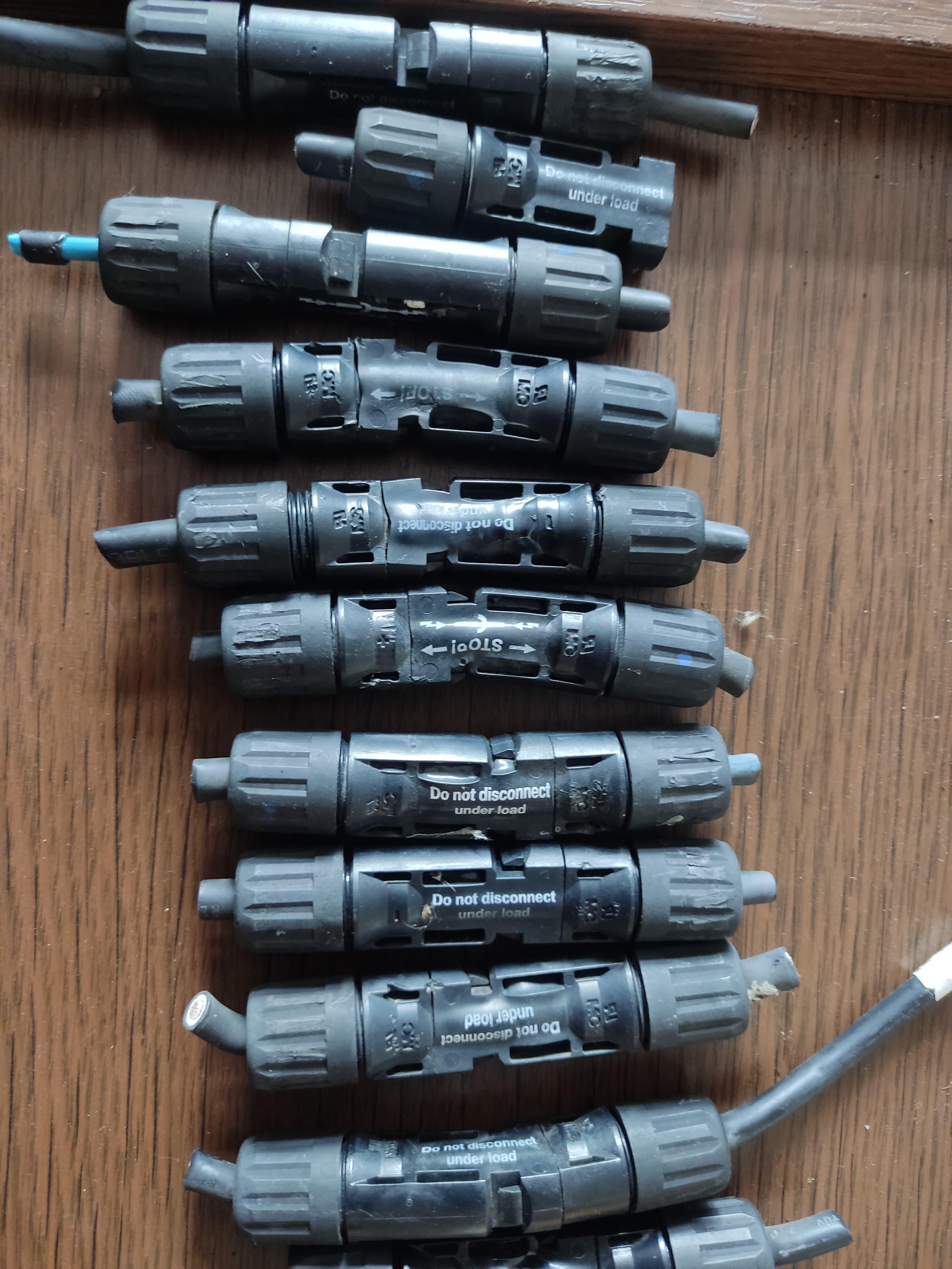
They are pretty decent. Most of the issues are happening at the start/end of the strings, where you connect panel to the "downlink" cable....and therefore MC4s from different vendors are mating. Yes, it is. Not really. They look like, but try to run 32Amps thru 230V AC plug for 8hrs in a row and you will see. Not to mention that 230V AC plugs are not IP68 rated. MC4s are. Oh yes....: WhatsApp Video 2025-01-11 at 19.53.19.mp4
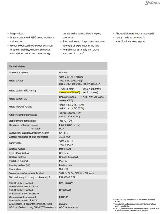 Most of the times the crimp itself is good, but the internal pins of the MC4 are not in the proper position (there must be audible click sound for each connector during it's completion, male and female..and then a third click as you plug them together.). See thread here: Speaking of incompatibility, the best is to buy a bag of MC4S, cut the connectors from the starting and ending pigtail of a PV string and crimp the same type of MC4 to that pigtail and to the "downlink" cable too. BTW: burnt MC4s are pretty common. A coleague of mine does repairs and checkups of large industrial PV parks and saw hundreds of burnt MC4 connectors already. Some of them were even smoking and melting just in front of him.IMHO, the possible approach in order to define a system is: Distinguish between systems that are built around a battery and the battery-less systems. Distinguish between systems that are meant for exporting back to the grid and the systems that are meant just for self-consumption, even if they can import from the grid or genset. Use AC coupling / DC coupling categories as @GreenFields mentioned. Explain future scalability scenarios and limitations. That would give you major characteristics that you can discuss with you client, for example, in order to explain how the system will work for him. BTW: It's not about the components or inverter(s), but about a whole setup. For example, a set of Victron Multis used in the offgrid mode would fall into a "self-consumption" category. Their capability of reconfiguration for exporting excess PV to the grid would be the "future scalability" then.IMHO, the inverters cannot be divided into clear and hard categories, as there are many possible modes, scenarios and features they utilize. And they can switch modes of operation too. For example, the Axpert King is a typical off-grid inverter, but it's capability of double conversion makes it more like online UPS. Some people would even say that it's a hybrid, as it can blend the energy from PV, batteries and grid together. On the other hand, contrary to classic hybrids, Axpert King is not able to export excess energy back to the grid. Similarly, Victron Multi is being perceived as off-grid, DC coupling inverter, but technically it's a full hybrid, as it can export excess to the grid and blend PV + grid together. And it can do both - DC coupling and AC coupling too. And last, some Axpert VM models are capable of mixing PV + Grid together, or even run without batteries, just with PV+Grid. And while they are not designed for export to grid, they can produce "spillover" and export small amounts of energy. So, it's technically a hybrid, although with a very bad management possibilities and definitely not a viable choice when you want to export surplus energy and got paid for it. Still, there are some main characteristics, and their combinations, that you can identify within an inverter in order to imagine where it will fit and where not: String Inverters Description: These are centralized inverters connected to a "string" of solar panels. Features: All panels in a string feed their power into one inverter. If one panel is shaded or underperforming, it can affect the performance of the entire string. Best Suited For: Installations with uniform sunlight exposure. Simple, flat rooftop systems. Microinverters Description: These are small inverters installed on each (or each two) solar panel (s). Features: Each panel operates independently, so shading or failure on one panel doesn’t affect others. Higher energy harvest in partially shaded or uneven installations. Best Suited For: Complex rooftops with shading issues. Systems requiring maximum energy production efficiency. Power Optimizers Description: Not inverters by themselves, but work with string inverters to optimize the performance of each panel. Features: Installed on each panel to manage power output individually. Combined with a central inverter for energy conversion. Best Suited For: Installations needing panel-level optimization but with a centralized inverter. Hybrid Inverters Description: These are capable of managing power from both solar panels and battery storage. Features: Allows solar energy to be used, stored, or fed into the grid. Provides backup power during outages (if combined with batteries). Best Suited For: Systems with battery storage or plans to add batteries in the future. Off-Grid Inverters Description: Designed for standalone solar systems not connected to the utility grid. Features: Works with batteries to provide energy during nighttime or cloudy days. Does not interact with the grid, but may switch to grid once the batteries are depleted. Best Suited For: Remote locations without grid access. Off-grid systems. Grid-Tied Inverters Description: Designed to synchronize with the utility grid. Features: Feed excess PV energy into the grid. Require the grid to operate (do not work during power outages without battery support). Do not support batteries. Best Suited For: Urban or suburban homes connected to the utility grid. Net metering setups. Battery-Only Inverters Description: Standalone inverters designed exclusively for managing battery systems. Key Features: Convert stored DC power from batteries into AC power for use in appliances or the grid. Often used to retrofit batteries into existing solar systems with separate inverters. Best Suited For: Retrofitting battery storage to an existing solar system. Dedicated battery backup systems. Regs, ChatGPTFor example, Hager HIC line is great, but just like you said - not really affordable. Not to mention the sheer size of the thing. There IS a proper way how to create ATS using two contactors, but they have to be mechanically interlocked, not just electrically. You can even buy all the necessary components as a set that's meant for reversing the rotation of 3-phase motors back and forth. But given my poor skills, I am a bit afraid to build it, so I resorted to Chinese crap, backed with some prayers A proper ATS using mechanically interlocked contactors: Mechanical interlock:
 Speaking of the old type ATS, there ARE arc-extinguishing chambers, Just check these U-shaped bits of metal: Well, another question is, how efficient is this cheap design. In the real MCBs, for example, this chamber is made of similar metal bits, but they are being hold by the two fiber-glass-epoxy boards normally. The closest to that is the chamber on the ManHua ATS photo, I would say.
 You are right @Eutechnyx, all these products are basically the same crap. Ampacity and mechanical endurance numbers are doubtful, so if one has to use these, it's always good to go for the highest possible rating within the product range.... and count that the real ampacity will be just a third or fifth of that value. For AC, it's still okay I would say, as the current goes through zero 100 times per second. On the other hand, I would never recommend anyone to use a Chinese MCB or PV switch in the DC applications. In the DC arcing is a huge problem. Any 10x38 gPV fuse in the DIN rail holder is much better solution there. BTW: That ManHua ATS looks nice from the mechanical point of view. Shame I did not knew about them before. I did not crack-open the new Geya ATS yet, it has to die first. Then, I will check how arc-extinguishing chambers look Anyway, it's already mounted and I can say that there's definitely a controlling chip, not the relay that was in the old types: The chip (MCU) is visible on the schematics. Accoring to manual it reacts to overvoltage/undervoltage too. Once the source #1 is back online, the changeover is not immediate, but the ATS waits for 3-5 seconds first and then it switches. That would not possible with relay logic.
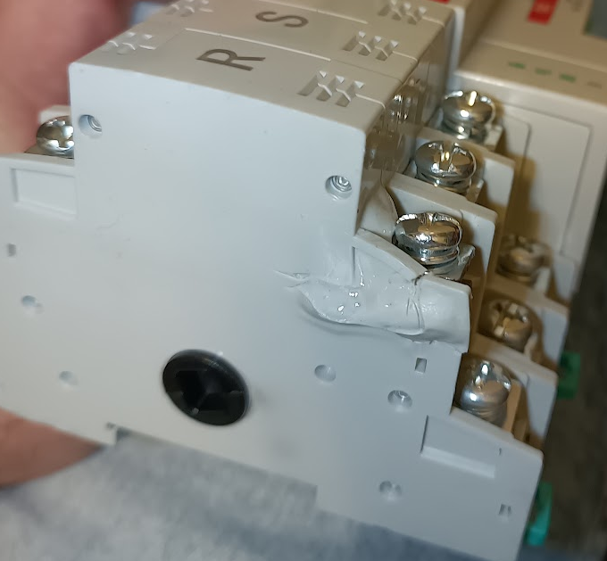
 Lessons learned: 1) If you have an ATS like this in you system, even though the higher current is just passing over the terminals and not via switched contact, check the terminals from time to time. 2) This type of screw terminals with square washers kinda sucks. Partial disassembly:
 Internal contact became angled and burned too: Two yellow spots on the opposite side of the ATS hit my eye too: Found out that the cause was the heat from two resistors that have no other purpose than to feed the indication LEDs. That's a sign of imperfect design, I would say: Anyway, I have two of these ATS in my setup, so I've already ordered a replacement. This time I went for a new version of the product that has better terminals. On the other side, this version is rated for Chinese 63A only, so I am pretty curious what the real ampacity would be Let's see how this will work:


 Automatic Transfer Switch - meltdown So, after a couple of years one of my ATS melted down. It was rated for 100A Chinese, so I would suggest that it can handle 32A European - well, I was wrong At first I was thinking that the internal contact burned, but after a dissection I found out that there was probably a high resistance on the screw terminal. (See how black is the copper wire under R terminal.) That caused excessive heating and meltdown. In the end, internal contact became so loose and angled that it started to burn too. As you can see on the first photo, there were 2 wires under each square washer. Wires were stranded, 6mm2 each, with crimped ferrule. The left wire is the input from the grid, the right one is going back to the floor heating that is 2260W (roughly 10A) as it makes no sense to power this from PV during our winters. The same logic applies to S (2430W) and T (2430W) terminals. Terminals on the top are the input from the PV system. When I tried to remove wires, the ferrule stayed in the spot, as it was welded in the plastic:

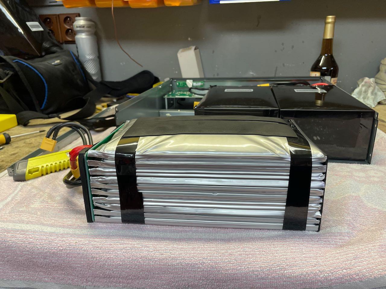
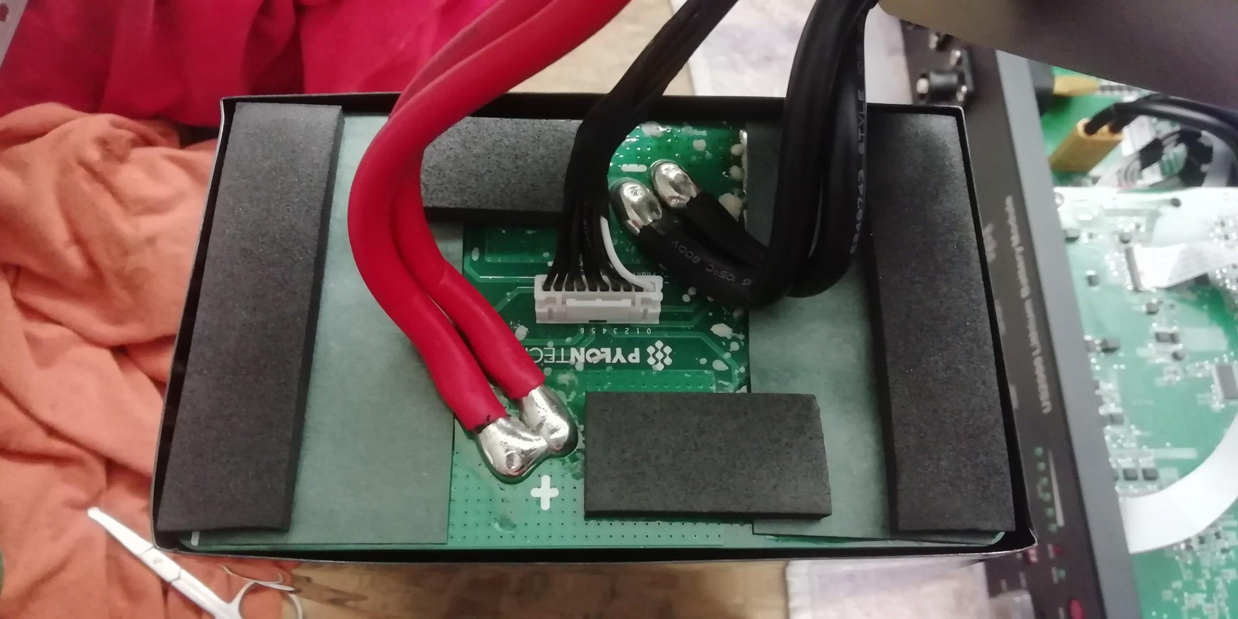
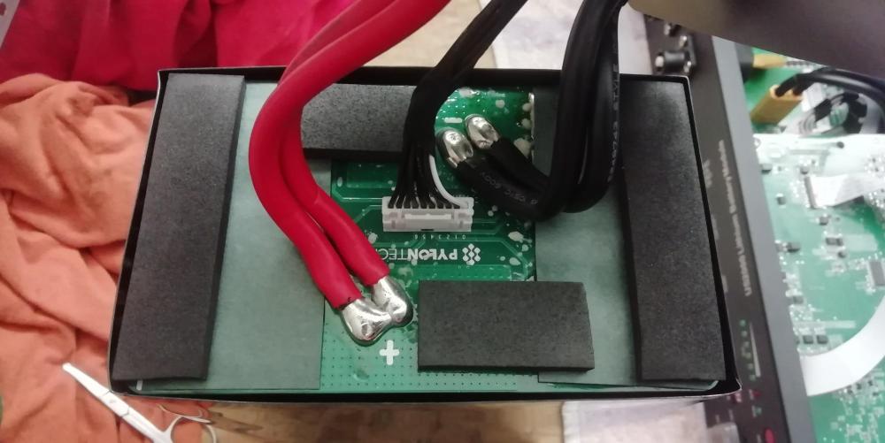
 Hi @Eutechnyx I'd like to help you, but for the US5000 the latest FW that I have is: US5000_V1.4_Crc.bin (for old chip) US_E3_V1.7_Crc.bin (for new chip) Never saw 1.9 and 2.0 file Anyway, should you find a suitable FW update anywhere else, just be sure to double-check what it is really intended for. Especially keep in mind that US5000 and UP5000 have a DIFFERENT FW. BTW: Pylontech is right, there's no need to upgrade the FW if everything is running okay. Just put the battery with the new chip and newest FW as the master and you should be good. Then, try to charge the battery stack few times and discharge it to a 20% SOC too. If that will work, you are OK. On the other hand, if the discharging stops before you reach 20%, then you have a reason for Pylontech support to send you an update Right?Also worth noting that most of the prismatic cells have aluminum case with just a thin blue coat (EVE for example). Therefore, it's best to put some kind of separator between the cells. Which consumes another space. Given how crammed the US2000 is using those 30 x 25Ah cells, it's obvious that you won't be able to fit 30 x 25Ah or 15 x 50Ah prismatic cells in that spaceUse BatteryView for the diagnostics. Then, charge all the batteries to 100% using grid and check with BV how they will behave during discharging from that state. Looks like undervoltage on some of the cells.Well, cells themselves are pretty cheap, as one 25Ah LFP pouch cell costs just around 25 USD. Just remember that finding a cell with the same dimensions on the market might be a bit challenging, of course. But the main problem is that the Pylontech repair will be quite a messy work: There are three cell packs in the US2000, each one sealed in plastic. Internal wiring of the each cell pack is 5S2P. You can't replace just one swollen cell, but at least the two that are connected in parallel. Chances are that some other pairs in the pack(s) will be swollen too. Chances are that all three cell packs will contain swollen cells. You have to carefully cut open everything, diagnose, unsolder/solder, and re-pack the cells tight, in order for them to fit back in. Not to mention that you have to precharge all the cells in the battery to the same voltage, as the internal balancer is not powerful enough to solve bigger voltage differences. IMHO, much easier approach would be to buy US2000 with a dead BMS board and just swap a swollen cell pack for the salvaged one. It's important to keep in mind that the cells are swelling for a reason: Overcharge, undercharge, overheat, etc. If you do not remove root cause of the failure, there's no point in fixing the batteries as they will get killed again. Most of the time it's like this: one or two cells are extremely swollen, while the rest of them is starting to swell too. A case of 29 perfect cells sitting in a box with the one that's looking like a balloon is .....unrealistic. Personally, I run a lot of Pylontechs too. Should they start to die, I will go for something with prismatic cells inside, as swapping a prismatic cell with the screw terminals is "a piece of cake" when compared to brain surgery skills needed for the Pylontech.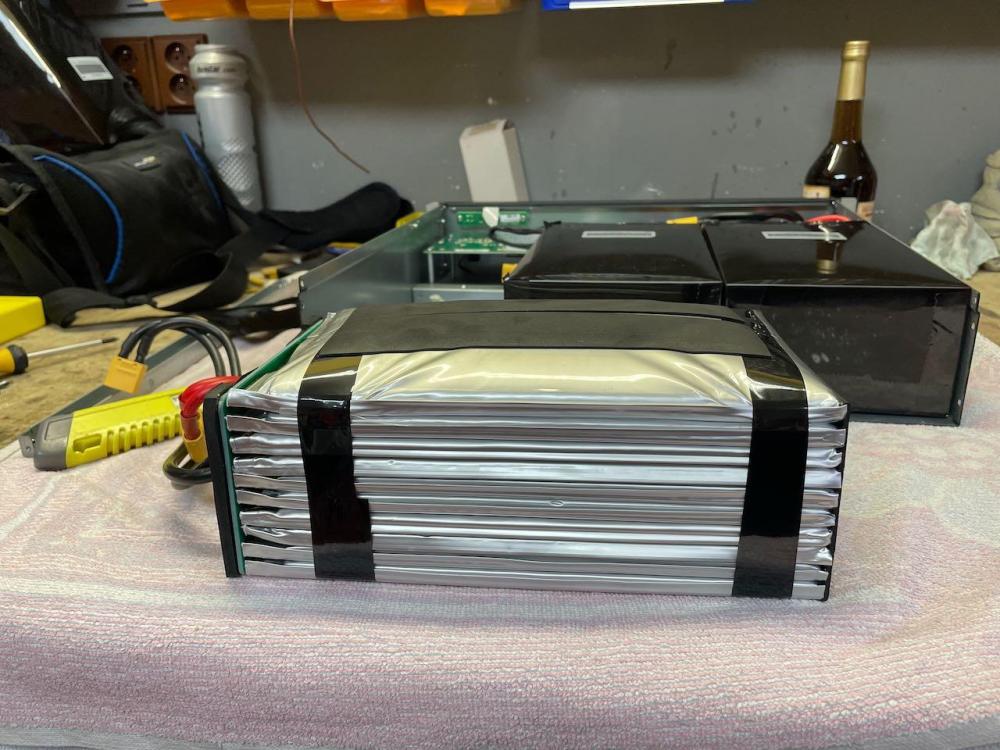
 God bless that one can un-brick the battery bricked by the wrong FW. Also, it's good to know that Pylontech FW can be downgraded. Something, that's less and less possible in the enterprise IT world.Good to hear that it worked okay for you. Since Pylontech is not publishing release notes for the FW, it's hard to say what are the improvements and if they are significant or not. Version 1.7 for US3000C is the first one that is able to report cells with the lowest/highest voltage/temperature in the stack, while not exhibiting "cell overvoltage" bug. Should work perfectly with the Victron Cerbo and CAN comm, if you have it. Personally, I am running version 1.7 on 8 batteries in a stack for years, connected to non-Victron inverters. And I'm not planning to upgrade the FW, since the setup works fine for me. Some of the newer FW versions are relevant for UP5000, since they allow higher discharging current that was not possible on UP5000 hardware in the past. (BIN file for US2000C, US3000C and UP5000 is unified.) Also, beware that version 2.2 might introduce some unwanted features, like the mandatory heartbeat - see the discussion led by @Tinbum on the previous pages. Anyway - if your battery has a fluctuating voltage issue, I would suggest you to contact Pylontech support via email first, since the solution might be a bit more complicated than just a FW upgrade.They are shipping with FW 3.0 preloaded for the old chip? And even using the old chip for the new SerialNumbers, after C2? Hmm, what a mess 😮The ZIP file method works great if the battery is not bricked. Once bricked, go with the BIN. If you have US3000C battery with ...C3... in the serial number, then try to flash one of the attached BINs. Both are meant for the "New Chip": Us_c_Nt_V1.7_Crc.bin US_E2_V2.2_Crc.binBTW, A lot of GUI errors is caused by the locale of the computer not being set to EN-US. Since the first flash ended at 80%, it was clearly the wrong firmware. It's crucial to find a correct one first. When in boot-loader mode, flash the extracted BIN file directly, not ZIP.Looks like you've flashed a wrong firmware version, which bricked the battery. Luckily, there's integrated "boot-loader" that works even if the battery is bricked. First of all, identify the correct version of firmware to be flashed and prepare the BIN file. Then, flash it using the instructions below:No, there is not. Although Phantom BMS has a broad command line capabilities, hardware-wise it is unable to actively modulate in/out current. Safety Mosfets in the BMS are just doing ON/OFF not PWM. More info: The BMS periodically communicates to the inverter desired charging and discharging current based on the SOC and state of cells. But it's the inverter that has to listen to this info and alter the current accordingly. If this communication is not working properly, then the current limit must be set on the side of the inverter and/or charger manually. When using HV batteries, working communication is mandatory. On top of that, some HV inverters have a configuration parameter that allows the user to limit current even further. Inverters for LV batteries have this feature always.