Youda
Members
-
Joined
-
Last visited
Everything posted by Youda
-
LinkPort cables are straight. Pin1 to Pin1 etc. Just get a standard 3m computer UTP Patchcord for 2 USD and it will work OK. (Cable you found is from the pylontech connection set and is meant for bms to inverter connection. Not sure whether it is wired 1-1 or not.)
-
Hi @Simon M. - let's divide problem in parts. 1) How is SolarAssistant (SA) connected to the LV-HUB BMS? CAN, RS485, else? 2) Ditch the LV-HUB for now. Form a totally separate group using just 8 daisy-chained batteries. Connect SA to the master and tell us how many batteries it will see.
-
🤣 Check the master battery gender. I bet it's a woman and since you've upset her, she does not want to talk to you.
-
@GreenMonster the problem is not the incorrect SOC, but the cell imbalance. Some of the cells have more charge than the others, which causes that their voltage goes up too quickly at the end of charging process. You need to either discharge these cells a bit, manually using an incadescent bulb for example, or wait for internal balancer to do it for you. The green SMD LED is not a cell warning light, it's an indication that internal balancer is working on that particular cell. Just lower the charging current to 1A (bench LAB power supply would be great for this), or even stop it completely. Then wait a couple of hours for the balancer to do it's job. Meanwhile, check the readings and lights. Once the imbalance is solved, continue with the slow charging. The SOC will reset to 100% automatically, once all the cells will reach cca 3,46V.
-
They are. But there is a New Lunar Year celebration going on in the Asia right now. Nobody will work for weeks. Upon returning to the job, they will clear their mailboxes so do not expect any answer if it will not arrive on the second day.
-
Can be set via CLI. It is super-complicated, great for getting extended info, but never worked for me when I tried to set the SOC. But the incorrect SOC is not your problem. SOC will auto-reset once all the cells ale balanced and charged to the top.
-
options login administrator pylontech console window other CLI commands to play with help pwr 2 pwrsys stat info 2 soh 2 config .... Good luck
-
Connect via BV to master, open CLI console and write down command: pwr Then check the text output. All the info about cells, temps and voltages is available to the master. Only thing that new FW does is that it puts small sample of this info into CAN protocol extension that Victron uses. So, just update the master and it should work okay with the Victron, despite all the others (or #3) will stay on the old FW. If you mess something, FW downgrade is possible in Pylontech.
-
Looks like that. RIP. Great question. Cannot answer this. Whenever I am doing FW upgrade, I do it one by one, without using parallel. Message unclear, please clarify.
-
Hmm, that sounds strange. You can go directly to the newest FW, no need for a phased update (I have 3.4 in my US3000 too). You can downgrade also. What else you can try: just turn them all off, and rewire the LinkPort0/1 cables in a manner that the last battery will be the master. Power on. Then try to connect BV and set Parallel = 3.
-
Hi @2una I have a couple of very old US3000 too, just like yours - with the RJ11 console port. A couple of tips: If the cable works for #2 and #3 it is okay and should work for the master battery too. (Of course, if the console port on the master is not physically or electrically damaged). AFAIK, a direct USB to RJ11 cable was sold for ICC monitor in the past. Maybe that's how you got it. CAN communication does not interfere with the serial console. They both run in parallel without any issue. So, you can leave master battery connected to Venux GX while playing with the console and BV. As far as I can remember mine US3000 worked the best with the BV2.0. Only after I upgraded FW they started to work OK with the BV 3.0.x. For the purposes of connection testing there's no need to check "parallel" and to enter the number of stacked batteries. Just select COM port and press OK. Even if the batteries are physically daisy chained, the BV will connect directly and show the values for the brick it is connected to. Works for master and for other batteries too. 115 200 baud worked for me every time, but the truth is the manual says that the console runs at 1 200 baud. DIP switches are for setting RS485 address of the master battery and for setting RS485 baudrate. They have no influence to the console. Sometimes the console of the BMS got stuck, especially if I tried talking to it via Putty too much, etc. If that's the case, just turn all the batteries OFF/ON in order to restart BMS. Beware of the power surge, caused by the empty capacitors in the inverter. The best would be to switch off the inverter first, but leave DC cables connected to the batteries so the capacitors will not get drained within a minute or two that you will need for that restart. Console does not reply when connected via Putty. It waits silently for a "magic sequence" that BV sends upon connection. Once that sequence is received by the BMS, it starts to accept CLI commands, sending replies etc. In this state you can use CLI that is built in the BV, or kill the BV and switch to Putty (or any other terminal emulator). TL:DR - I would suggest to restart the batteries

-
That really depends on the inverter. If the inverter wants RS485 as BMS input, you can skip the LV-HUB in the last step. That's the case for Axperts, for example. If the inverter wants CAN BUS as BMS input, you need to supply CAN. That's the case of Victron, etc. On top of it, there another catch: with the RS485 the inverter firmware has to support not just the BMS protocol itself, but also a total number of piles and Pylontech batteries connected. AFAIK, some inverters with RS485 BMS IO support just 2 piles of the batteries. Not being able to address more. With CAN the number of batteries and piles does not matter. Once the inverter supports CAN for BMS, you can connect all the batteries and piles you have.
-
Just a note for the curious: Ports A/CAN and B/RS485 on the US3000C are having both protocols in each port. So the A is technically CAN+RS485, B is CAN+RS485 too. Daisy chaining of multiple "piles" together runs over RS485 protocol, the conversion to CAN protocol is done by the LV-HUB in the last step. Daisy chaining of individual bricks within a single pile uses RS485 protocol too, but this time via LinkPort0 and 1 ports.

-
For a shame no. The longest daisy chain in your case would look like this: CAN 1. US3000C 2. US3000 3. US3000 4. US3000 5. US3000 6. US3000 7. US3000 8. US3000 9. US3000C 10. US3000C No LV-HUB needed for the above. Not possible to utilize 11th US3000 battery. FW update required. To be honest, the above would be the preferred way for me, in order to keep things as simple as possible. I would test it first, then sell the 11th US3000 and buy US3000C instead. Then, the max daisy chain would be up to 16 bricks. The other way is to use LV-HUB, just like your original idea. The only comment is that the groups are to be chained via connecting A/CAN to B/RS485. Not A to A or LinkPort0 to B. https://www.ostrovni-elektrarny.cz/docs/us3000c-manual-eng.pdf (see PAGE 23 - Multi Grouping)

-
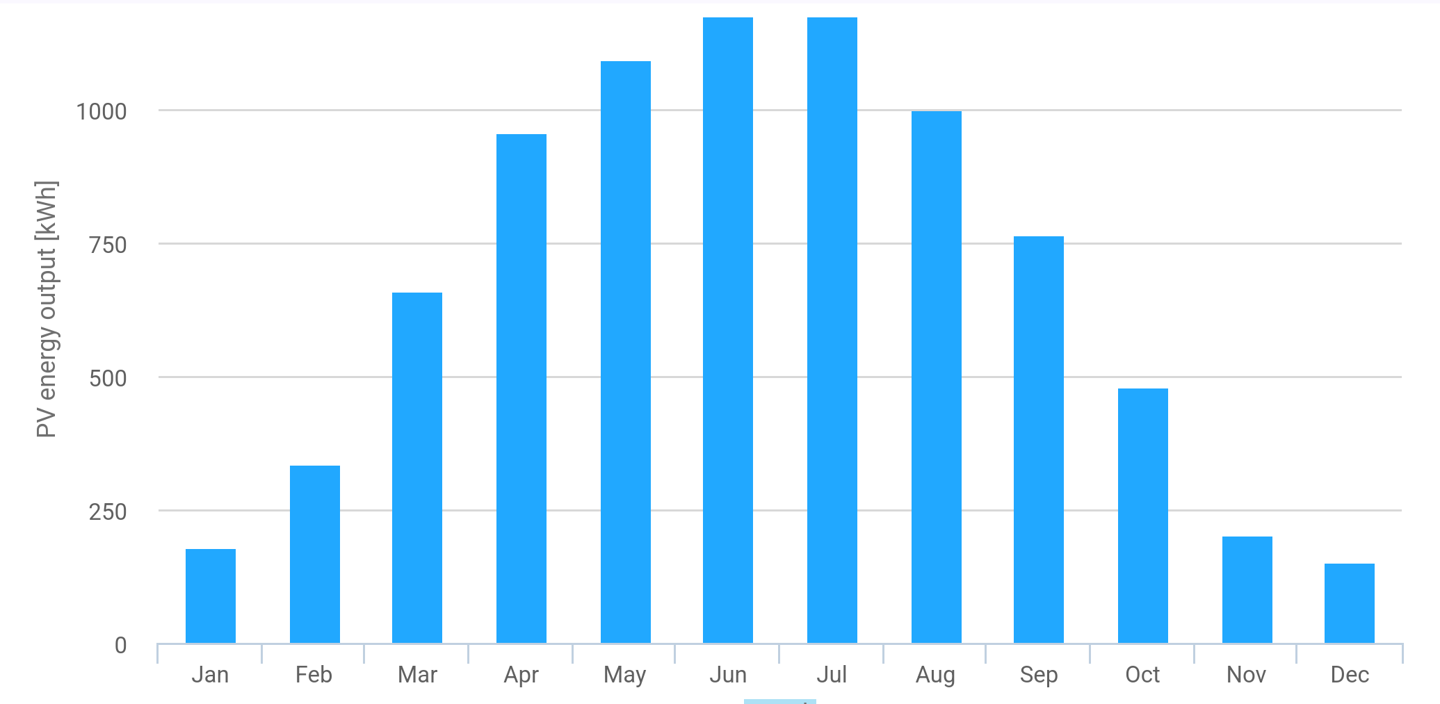
In my case, it's for the hot water baths and showers. You know - having girls in the house means that you need a LOT of it 😂 BTW: For a shame, here in the Europe PV works really great from the start of February till the end of October, but during November-December-January, the sky is dark, cloudy and the snow is falling too. So the winter solar yields are totally unusable for anything serious PVGIS Calc 10kWp:

-
You can. I am running 4kW of heating elements on my solar system every day, from spring to fall, without any issues (Europe). Also, charging EVs from my off-grid solar quite often. It's 7kW of load. With your system a couple of heaters will be no problem.
-
IMHO, this looks exactly like the inverter transitioning from CC to CV.
-
Well guys, I would not blindly trust any voltage measurement that is: - measured by the inverter itself - performed while the inverter is still connected to the batteries and AC loads are ON, panels are ON. Who could be 100% sure that the voltage fluctuation is produced by the battery, not by the inverter? My 2 cents...
-
Because it is not. Just try it: Get the batteries to this state of being almost full Wait for the BV to show 52,6V Connect the multimeter to the DC terminals of the inverter and measure the voltage. You will not see 53,5V there. Can you handle this?
-
AFAIK, in case of Pylontech US, the BMS declares 100% SOC once all the cells are at 3,48V or over and the voltage difference between lowest and highest cell is less than 30mV. Below these values, BMS will appear to stuck at roughly 90% and there will be a small jump to 99 a 100 finaly. Reason is that it's very hard to calculate SOC based on integrating Amps at these stages. Writing this just from my memory, the exact numbers can be extracted using CLI. If you continue charging, the current will be accepted by the battery but the reporeted SOC will be still just 100% (well, sometimes GUI can glitch to 101% but that is an error). This is "balloon full" state for the Pylontech. Anything above is the margin before the "balloon popped".
-
Also, it is important to understand that physically, there is nothing like 100% SOC for the cell. A LFP cell is just like an air-filled birthday party balloon: When is the balloon 100% full? Is it the state when you blow another air molecule into it and it pops? If so, how does it depend on the balloon's temperature? If that 100% full mark is somewhere lower, where more additional molecules would safely fit inside, can I blow some more air into the balloon? How much? The "curse" of LFP is that they are so energy efficient that you can damage them even with just 1mA of charging current, if applied for a long time. With Lead-Acid batteries that would be absolutely no problem, but LFP stores lithium ions in the hard 3D lattice. If there's no more space for incoming ions, the lattice will crush and gas-mix of O2+CO2+phosphate will be produced. And that is the reason, why some cells are swollen. Either they had manufacturing defect (most of the time it's the the separator failure), or something was hitting them with just a few miliamps of current for a long time, so the lattice started to break. Yes, it would be great to have a BMS that can perform sophisticated monitoring of the cells, but in reality all the BMS-es are just measuring temperature, voltage, current and doing time-based integration of Coulombs in order to "guess" SOC. But keep in mind that more complicated electronic device is, more likely will it fail. Not to mention that it will cost more, consume more energy and produce more heat. While the Pylontech BMS is far from being perfect, the solution is not to improve and over-engineer the BMS itself, but to configure whole solar system in a way that the margin between "balloon full" and "balloon popped" states will be reasonably wide and safe.
-
Technically the inverter is not sending voltage, but it's sending current. It's so called "CC mode". The current is being split between all the batteries based on their internal resistance, interconnection resistance and willingness to accept charge that changes with SOC of the individual cells. For the same voltage, different batteries will have different charging current. The 53,5V is the voltage value that the inverter is looking for to stop sending current (stop charging). Some of the events that signalize end of charging (CC mode) and transfer to the CV mode: If the battery reports 53,5V the inverter stops charging, even if the cells would still accept current. If the cells stops accepting current, the charging is finished. This might occur even before the cells reach 53,5V. If the BMS reports 100% SOC, inverter will stop charging. If the BMS reports "Advise Charge = 0A", inverter will stop charging. If the BMS reports one of the many possible Errors and Alarms, inverter will stop charging. Most of the time CMOS will be activated by the BMS, so even if the inverter would still continue with the charging, the actual current will be zero amps. Pylontech BMS is really doing nothing to the current that is flowing from the inverter. It has two protective MOSFETs (DMOS and CMOS), that are being operated in the ON/OFF state based on alarms. No analog current modulation feature is in the BMS.
-
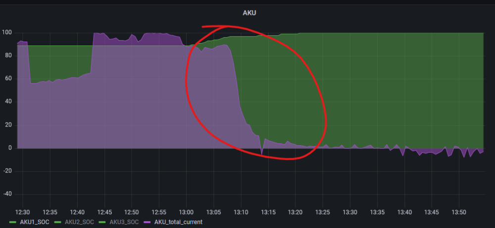
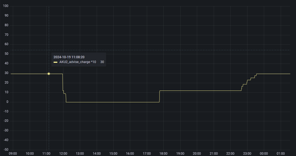
This is normal. As the cells in a module are reaching full charge, their ability to receive charge drops gradually. Therefore the charging current drops too. For example, here's the charging current of 8xUS3000 in one of my stacks: The gradual drop of the current is caused by the cells, it's not something that BMS or Inverter does. For each battery in the stack this curve will be slightly shifted in time. That's because each battery has a slightly different charge, therefore slightly different ablility to receive current. Exactly as shown on your BV screenshots. You can observe this even by just looking at the LED bars of the individual batteries - some of them will be fully charged already (LED bar goes off) while the others will still being charged (LED bar with one blinking LED). Once again, it's pretty normal that you see a different amps for each battery in the stack and the BMS/Inverter has nothing to do with that. Yes, the BMS IS able to tell the inverter what to do, but the charging information is sent for the whole stack, not for individual batteries. For example, this is the info, that BMS sends via CAN BUS during charging of the above mentioned stack of 8 batteries: charge with 300A max charge with 120A max charge with 100A max charge with 90A max charge with 0A max Yes, some of the batteries might experience manufacturing defects, resulting in premature damage. That's what warranty is for. But the examples shown in this thread, where 10+ batteries "blown" at once are not that case.
-
Pylontech firmware is not actively modulating charging current, nor voltage. It just passes through whatever the inverters sends down the wires. And the inverter (when BMS communication is established) is sending whatever BMS asks for. All the Pylontech US firmware versions, that I've tried, asked for 53 250mV (53,25V). Since some of the inverters are not able to set charging current in such a fine steps, they will charge to the nearest possible value, that is 53,3V or even 53,5V. It would be nice to have a Pylontech firmware that would ask for a charge voltage of 52,6V but it is nonexistent. (if you exclude the option to hack BMS protection values via RS232 console and throwing your warranty out of the window). Why some setups experience swelling while the others don't: Depends much more on the inverter. How precise and fast it is, how much it overshoots. Depends on the wiring quality and battery bank capacity. Larger banks are capable of surviving more abuse. Smaller banks degrade faster. Depends on the varying AC loads. Big AC loads that are being turned ON and OFF quickly are the worst, as the energy from the PV panels is already in the inverter and when the load is suddenly OFF, that energy spike has to go somewhere. Most of the time, it goes to the grid (for hybrids) or to the batteries (for off grid). One example of such a nasty load is induction cookstove. Can't tell you how much time of abuse it will take before the batteries starts to swell as I am trying not to abuse mine, charging them to 52,6V or 52,7V and they are fine so far. Even the ones that I bought in 2018 are still working like a charm.
-
@Vanman did you found the reason? I would say that the opener was holding the "stop" or "close" contact in a closed state. Therefore, gate does not react to subsequent commands from remote.