


Youda
Members
-
Joined
-
Last visited
Everything posted by Youda
-
@Erwin Bakels I have 3 CAN ports on my PLC device so I dont need LV-HUB. Got them as 2x8 and then each stack into own CAN port.
-
Firstly, thanks for the detailed reply. I really appreciate it! 1. Can you explain this a bit more? Minisplits are great, but they work on the principle of blowing a very cold air from one point. Sitting under an indoor unit is not comfortable at all. Ducted AirCondition works on the principle of distributing cold air using multiple points across the whole space. Therefore the speed of the air is minimal, noise is minimal too and the temperature is very even across the room. On the other hand, ducted A/C needs to be hidden in the ceiling which might not be possible in a typical SA house. Not to mention that you need a specialized installer for the system like this, which might become costly. Generally, ducted A/C is a good choice for the new high-end buildings, usually combined with air filtering etc. Not at all. I've just traveled a lot in my previous job, spending some time in the middle-east. Their office buildings and houses are awesome. For example check some villas and condos that Emaar Development is building in the Emirates. That really works well. On top of it, exterior blinds are MUCH more efficient than the interior ones. It's simple - exterior blinds blocks the heat on the outside, even before the radiation enters the room. On the modern houses you see them a lot.
-
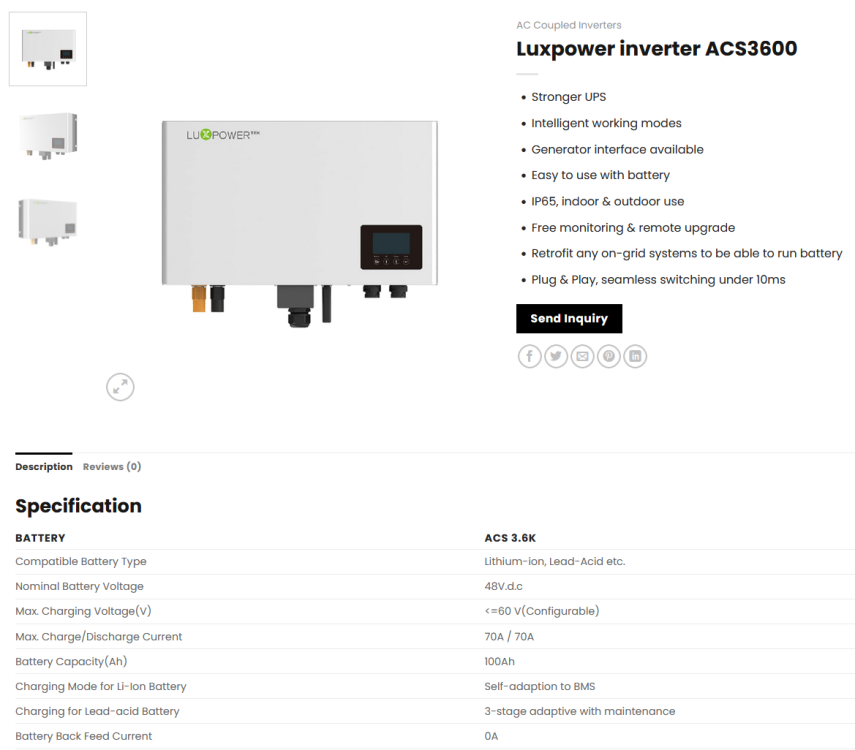
No. Inverter must be connected via RS232 cable to SA. Batteries have to be connected via CAN, RS485 or Console cable to SA. In your case, if you have Shoto batteries, there's a dedicated RS485 cable for it:

-
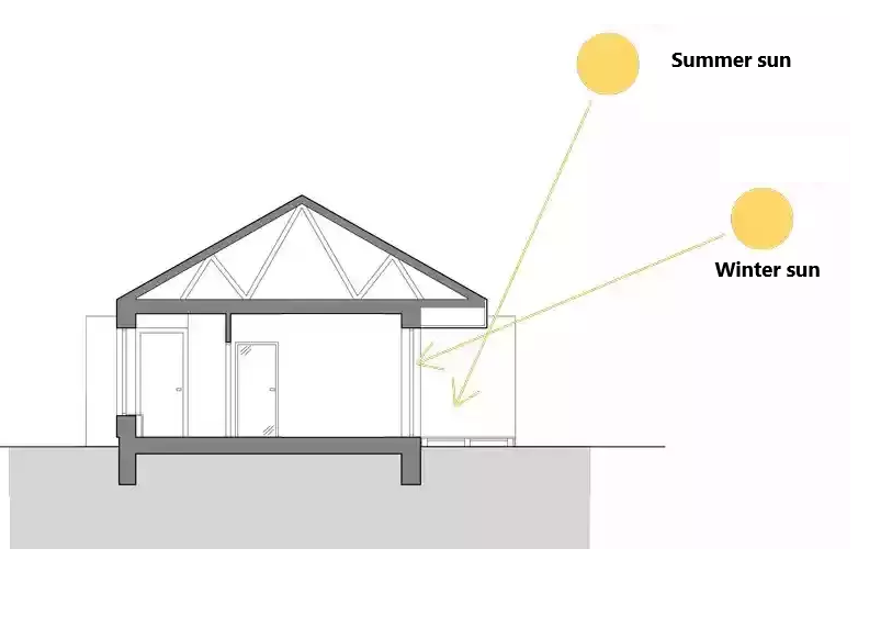
Personally, I've bumped into these: It's better to keep A/C running at very low power 24x7 than turning it on full power (and full blow) after getting home from work. (Cool wind will make you sick quite fast, if you will run A/C on full power.) A/C + windows open all the times does not go well together. Creates a lot of water condensate dripping from the external unit, but the cooling effect is minimal. Cold air falls down and cannot cross obstacles. A/C works greatly for open spaces, but will not cool a bedroom hidden behind a corner. Mobile A/C is just loud and clumsy, makes no sense to invest in it. Mini-split or multi-split is much better, with duct A/C being on another level completely. Disadvantage of multi-split is that once the shared external unit fails, you have no A/C at all because of missing redundancy. External unit is quite for first couple of years, but will become louder over time. From some angles you hear nothing, while from the other it's unpleasant. When the external unit is mounted on the wall (brick) sometimes I feel vibration despite being in the room that is most far from it (and no vibration in the room adjacent to the actual wall with the external unit) The Sun is 1000x more powerfull than A/C. The best combination is A/C + roof overhangs above the windows, in order to limit sunhine heating the floors.\
-
Keep the inverter in a cool and ventilated place. Also, protect it from collecting excessive amounts of dust. Do not put high inductive loads on it. (IE: do not put 5kVA motor on a 5kVA inverter) Follow installation instructions, especially when comes to proper grounding, SPDs, input voltages. IMHO, there's not much you can do proactively, if you don't want to crack the box open and replace one third of the components in advance. Which, to be honest, nullifies advantage of a cheap box.
-
Just keep in mind that solution has 2 parts. Part 2 being establishing that data communication from the BMS to the SolarAssistant, as described above.
-
That looks reasonable to me! BTW: BMS boards normally take just under 5W or so. Except for the time when they are balancing. Hybrid all-in one inverters consume at least 60W when idle, but significantly more (150W+) when the PV production is high. You can notice that the inverters got very hot (and even start fans) when under high AC load or when the incoming PV power is high too.
-
- low quality caps - heat - overload One can have his Axpert proactively recaped with Nichicon, but the question is whether it makes sense. Given how much Axpert units is being sold every year, the failure rates are amazingly low. Personally, I would just take care of heat. Once the Axpert dies then it can be repaired and recaped, together with new FETs and other semiconductors.
-
Yeah, that's what I hear all the time. Mainly women are telling me this
-
Hi @PhilT based on all your info, this should be the battery and inverter you have: Now, back to your chart: #1) Is rougly 2000W of AC load #2) Is the discharge, running for cca 1,5hrs (= 3kWh discharged). Since it's LFP chemistry, and the curve is nicely straight, it's definitely data provided by BMS that is integrating current over time in order to calculate SOC. At 1:30 there's just 0,4kWh stored in the battery, which is almost nothing. Note that your battery has 3,4kWh in reality, but usable is 3,2kWh and BMS is set by the factory to report SOC=0% once you've depleted 3,2kWh. That's why they can guarantee you to use whole 0-100% range, since technically the battery is 0,2kWh + 0-100%. #3) Is the point where BMS of the battery realized that the voltage of LPF cells raised back (becase the huge load was removed) and therefore it "corrected" it's SOC calculation. That was a mistake. In reality, the energy has been consumed and the real SOC should follow ORANGE highlight (#5). #4) is the point where voltage of the battery dropped slowly under a factory-defined threshold where BMS again "corrected" SOC calculation to ZERO and initiated recharge from the grid. Summary: It's normal for LFP cells that their voltage goes down and up based on the load, if that is quite high, relative to the cell capacity. The nominal battery energy (3,2kWh) was already consumed when the BMS reported SOC=0%. Strange SOC curve is just an error produced by the BMS calculations and corrections. This might be fixed by a battery firmware update in the future, if the manufacturer decides to make one. I don't like the fact that specsheet of the battery allows charging to 3,6V (it's 16cell battery), but I hope that the warranty is long and will cover battery swelling. Apart from that, there's nothing really bad going on and I would say that the system is operating as designed. If you need more runtime, you have to add more batteries. Hope this helps.


-
Issue identified. Will reply in the evening.
-
Make, model and power of the inverter. Make, model and capacity of the batteries. Is there a data communication cable betweeen the inverter and the batteries. Are you able to see individual cell voltages somewhere in the GUI or the APP where you got that chart from. Whether there are photovoltaic panels connected to the inverter, directly or via another AC coupled inverter, for example. Allowing discharge down to 6% is really heavy use of the batteries. It's great for squeezing maximum from the batteries, but might hurt them (depends on cell chemistry) if is happening regularly.
-
AFAIK, it was Solis + Dyness vs. Solis + Pylontech. Presented efficiency was different, but really terrible in both of the cases. You asked there why is the OP comparing systems that have different components, loads, number of panels etc. Which was a valid point. The difference in those efficiencies was caused by the fact that one system used and generated 5kWh per day, while the other 7kWh per day (or something like that). Should we get a comparison with the system that generates and uses 100kWh per day, the presented efficiency will be superior Should we use a different method to calculate battery efficiency (for example using values from the BMS), the lithium efficiency will be superior too.
-
When asking questions like this, it's beneficial to include all the important info. Otherwise it's pretty hard to answer correctly. For this case: OK, purple is SOC and right axis would be SOC%. What is Orange, Blue, Green, Red? What are the Units on the left axis kW? How do you measure each of the metrics? How do you get SOC values, from BAT Voltage or from BMS? What are we talking about, hybrid PV, off-grid PV, Server UPS or a coal Power Plant? What are the parameters of the system? Why did you designed the system in a way that it discharges battery to 6% every day?
-
Yes, there were 2 or 3 additional screenshots from the inverters APP that clearly showed what's going on here. I elaborated on it for half an hour to explain. Shame that our friend spammed so hard that it got all deleted 😐
-
Hi@Bobster. you are missing important part of the original posts and threads (that were deleted by moderators because of excessive spamming I suppose): There was a screenshot of the inverter's LOG, where each day it was reported roughly 5kWh as charged in the battery and 3kWh as discharged from the battery. Efficiency was calculated as the ratio between charged/discharged. All these inverters are hiding their own self-consumption and instead of the real measuring on all the possible points, they measure just on a few of them and then calculate the other values with the use of constants. For example: Measure incoming PV power, integrate over time for kWh. Measure outgoing AC, integrate for kWh. The difference between incoming PV kWh and outgoing AC kWh is reported as charged in the battery. Since there is 80W of idle self-consumption, it's roughly 2kWh per day that get's lost in these calculations. I'm pretty sure that the real lithium battery efficiency in this case is way over 95%. That would be visible on the numbers directly from BMS. Numbers from the inverter are more about whole system efficiency, which in this case is really 60% roughly, due to the low ratio of energy generated, stored and consumed when compared to energy needed for just idling the inverter.
-
Already answered you in one of your 5 threads where you were spamming with this same question. Since I see that those threads got deleted by the moderators because of your spamming, I will make it short this time: This is NORMAL. Every inverter has internal self-consumption, and they normally try not to report it. For these small inverters it's around 2kWh per day just to keep the box runnnig and fans blowing. Therefore, if you charge 5kWh in a day but the inverter consumes 2kWh, then you have just 60% efficiency. How to improve it: Charge and discharge 100kWh in a single day and you will see more than 90% efficiency (100kWh from PV vs 2kWh of inverter's self-consumption). Of course, in order to be able to do it, you need big battery, big AC loads and many kWp of PV modules. Clear?
-
= Lithium battery fully charged + export excess energy to the grid disabled. Normal. = BMS of the battery not talking to the inverter. Inverter guessing SOC based on the battery voltage. + BMS of the battery not connected to the SolarAssistant. How to improve this: 1) Kodak OG7.2 is an Axpert variant. Factory firmware sucks. Search for "patched firmware" from @Coulomb and @weber 2) Shoto Lithium(still have it in this system?) is based on PaceBMS or something similar I suppose. Set it for Pylon protocol and connect it to the SolarAssistant via CAN-to-USB cable and get these two talk to each other. Then SA will have correct SOC and will be able to control the inverter based on it. PS: SA supports Pylon protocol for sure, but maybe it can support Shoto/PaceBMS directly too. Work with SA support to clarify the best protocol mode pls.

-
Hi @jjvvuuren thanks for the feedback from the previous tries. Shame it does not work. To summarize, you want to use you system like this (correct me if I'm wrong): Working like an online UPS (backup power supply) Battery have to stay fully charged at all times, and discharge only during power outages or loadshedding Self-consumption of the inverter should be satisfied from the grid Recharge depleted battery from the PV I'm afraid that the above is not possible with Deye directly, therefore we have to use a couple of tricks. Deye always uses PV and Battery for it's self-consumption. Once there's no PV, it starts to take from the battery. Therefore we have to continuosly refill the battery from the grid, if we want to keep it charged. This is something what "Zero-export Power=100" should do, as it would force inverter to pull 100W from the grid and that 100W would go to the loads or to the battery to keep it full. Since it does not work apparently, there's just one trick that I can suggest: Return back Zero-export Power=20 Set the values on WorkMode2 screen this way: How this should work: it tells the inverter to keep battery at 95% SOC at all time, using the grid. You dont' have to wait for the night, just disconnect the PV and wait hour or two to check how it behaves. If this won't work then I am out of ideas, sorry.

-
@jjvvuuren Set Zero-export Power = 100. Save and check how it works now.

-
While it is technically possible to combine some models of batteries with the others, there's a lot of caveats and limitations. Some of them being: Voltage Cell count Chemistry BMS communication Warranty Based on that I can't recommend doing so. Upgrade as per manufacturers guidance, or sell what you have and rebuy from scratch.
-
I assume that the picture is from the manual, so it might not be 100% accurate. Can you take a look directly at the inverter? If you have it already, of course.
-
Hi @jamila To be honest, 6 panels for a family of five is almost nothing. Assuming cca 500Wp per panel, that would be just 3kWp, which translates to roughly 15kWh per day in SA. Not so bad on a first sight, but there's a lot of gotchas: If the system is connected to the grid, and you start any load higher than 2,5kW and it's not perfect noon, then you will be drawing that missing power from the grid (or batteries.) On a cloudy/rainy day the power drops quickly. Next day, you have to satisfy the loads, but to charge the flat battery at the same time. If your house wiring is 3-phase, but the PV system is 1-phase, then the benefit is minimal. Etc. If you are not electrician, installer or PV geek, then I would advise you to get in touch with a reputable PV installer (or company) in your area, have them check your current PV system, loads, house wiring, family needs and then design a detailed plan of PV system upgrade based on the calculations. If you want a quick answer, then from my experience the reasonable solar for a family house starts at 10kWp of PV (cca 20 panels), 20kWh of lithium battery, 10kW of inverter power. For offgrid use, 1-phase wiring and inverter makes sense most of the time. But like I said - check your situation with an installer. Not to mention that I've seen 1-phase solar in a 3-phase house. Or a PV system, that was configured as backup only, not helping the house loads at all.
-
PV1 + PV2 = MPPT1 = max 32A total. Intended for east+west arrays combined. PV3 = MPPT2 = max 20A. For main North or South array. BTW: on the bottom of a physical inverter the PV1 + PV2 should be grouped in a square symbol. Aren't they?
-
Hi @Riaan Eloff Yes, it does not. Pylontech's BMS has very limited protection capabilities against overcharge of this type - voltage spikes caused by AC loads and PV power fluctuations that are routed by the inverter to the battery. It can protect the battery against trying to charge it to 56V (for example) with a constant energy flow, but not against the spikes. Normally Pylontech BMS relies on the active communication with the charger (inverter in this case). Once the BMS sees that cells are almost full, it asks the inverter to lower the charging current. Similarly, when BMS sees Cell High Voltage, it generates High Voltage warning event and the inverter is supposed to stop the charging so the internal balancers can solve the Cell High Voltage issue. Cell Over Voltage Event is even higher level. For a shame, many inverters are not listening to the BMS requests and events correctly, nor they act as being asked. Axpert(s) being one of them. Not really. The damage was a result of what the original installer did and configured. Following manuals and specsheets blindly is one thing, having enough experience to know what are you really doing is completely another thing. Float voltage too high. This is something what installer should know and set correctly, based on the actual experience with Pylontechs + Axperts. If you want to minimize further damage, set your inverter according to what @Coulomb says above. That swollen US2000 battery is K.O., but if you are going to replace it with a new one, it definitely makes sense to prevent the same damage to happen again. BTW: If you want to know more about the Pylontech US batteries, just check some posts my thread here:


