WillHza
Members
-
Joined
-
Last visited
-
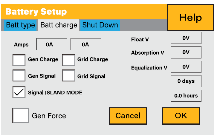
Please do not use what I say below as the right answer, this is just my understanding based on my experiences and research. I also do not know how your grid power is transformed and ultimately delivered to your house, other than what is available on the internet (380V 3-phase or 220VAC single phase 50Hz, euro style three pin L-N-PE outlet sockets). So I assume a lot of things based on South African grid standards, which are very similar to many western European grid designs (IEC derived standards). To answer basically, if you have no legislation or guidance from your utility (unlikely, but maybe just ignored due to the nature of the situation) you can actually build a system WITH the bonding of the input and output neutrals or WITHOUT bonding the input and output neutrals. BUT each scenario has it's own set of rules that must be followed in order to make a system that is safe to the user. Safe to the user means you have a good Earth Fault return path (PE) to the generator/transformer/inverter supplying the power and a rapid disconnect in the event of someone or something touching the live wires in the system. In this event an overload switch (Circuit Breaker/CB) and more importantly an earth leakage detection switch with or without an overload (Earth leakage/RCD or RCBO) should rapidly disconnect the load should 30mA or more current imbalance be detected on the circuit (considered the non-lethal limit). In both cases this can only work if there is a connection at some location after the step-down transformer of the Neutral wire (N) and the Earth Fault wire (PE). As a rule there should only be one PE-N bond in the circuit, otherwise currents can be allowed to flow continuously on the PE wire and other conductive metal objects such as casings/waterpipes/gas pipes/etc, which they are not designed for. Scenario 1 : When you are making an installation with the In/Out Neutral permanent bond you are assuming that the electrical utility supplier has made this PE-N bond connection and maintains this connection somewhere upstream/before the meter . It may or may not be true in Australia that this is the case. The utility will can manage the PE-N bond for you whether in on-grid or off-grid mode. You would not make your own PE-N bond in an off-grid scenario in this case. This is not allowed in South Africa. Scenario 2 : When you are making an installation and are not doing a permanent In/Out Neutral bond at the inverter, you are taking responsibility for managing your own PE-N bond when you are running in off-grid mode. This is a requirement in the standards in South Africa if you are installing the inverter some distance from the utilities PE-N bond (a home installation for example) and it may or may not be a requirement in Germany and the UK also. In this case you will need to rely on a relay/contactor controlled by the inverter that bonds the PE and N when in off-grid mode and disconnects it, to make use of the utilities PE-N bond, when in on-grid mode. Some inverters contain this bonding relay inside the unit and some only provide a control signal output so that an external bonding relay/contactor can be installed external to the device. These bonding circuits are usually activated or deactivated in the system software or with external jumpers. The Scenario 1 is probably only a good idea if you have a well functioning and maintained grid network and also an honest population or well protected grid facilities. In places with opportunistic criminality, the PE-N bond is commonly stolen for it's copper value from the utility side, leaving the user vulnerable to electrocution should a fault occur. Also if your incoming isolator switch isolates the Live AND Neutral wires (a requirement in South Africa), then by opening this switch you break the Neutral to the utility, and therefore also the utilities PE-N bond from your backup power circuit. Also worth mentioning, if you have a cheap/small UPS style battery backup inverter, you may find that the neutrals are already bonded, and they also provide no facility for signalling when the inverter is in online or offline mode. These inverters should never be permanently installed and are best only ever plugged into a wall socket to provide a temporary power bridge during momentary power outages to small appliances in close proximity. To others reading this, if I have made an error above, I'm happy to be corrected. Examples: See this video of setting up the Huawei Grid tied inverters "off-grid backup box". At 5mins 40sec they talk about setting up the system for the bonded neutrals and for unbonded neutrals scenarios "according to the local power grid standard" using bridging jumpers. On a Sunsynk/Deye it is called "Signal Island Mode" in the settings, and controls a low current signal output (5kW/8kW/16kW). Screenshot provided previously of the wiring connections.
-
-
I think @BritishRacingGreen answered you correctly based on the assumed question, @TaliaB did the same with even more technical explanations, based on certain assumptions. "Is it OK?" is a broad subject, and each person will answer based on their assumption of what you are asking, where you are asking from, which inverter you are asking about, and for whom. Are you asking if it is "legally" OK (or even mandatory) to bond the incoming and outgoing inverter neutrals (according to the electrical laws/standards in your country or utility - of which I don't think you mentioned)? Are you asking if it is OK from an electrical safety perspective (to the end user, or the inverter service person, or the electrical utility supply operator person)? Are you asking if it is OK for the inverter or other electrical appliances (will it damage them in any way, under normal and/or abnormal circumstances)? I don't have the clean cut answers unfortunately, but it would be fair to say that each of the above may be answered with "depends" based on the specific scenario. Perhaps if you are more specific, someone can give you a more specific answer. For example, here is an extract from a Sunsynk user manual which shows the incoming and outgoing neutrals separate in one diagram but also coupled in another. These different wiring methods are based on different geographical region standards or the standards of a specific electrical utility or even the exact electrical design of how the wiring gets from your specific local transformer to the electrical box in your specific house (TN-S/TN-C/etc). Do not take this diagram as truth either, as I think they get it a bit incorrect in part because even they do not know the rules for every region/utility, and it was probably a mistake to include it, for it has sent many on the wrong path based on incorrect assumptions of locality and system design. Hope this info helps, sorry to hear of your electrical supply situation. It is familiar situation to some of us also (South Africa), though not quite as bad as you have described (yet?)

-
-
-
-
-
-
Thanks @Sc00bs for sharing. Not really impressed to be honest. He begins by taking a snipe at electricians for not being able to read, and then proceeds to reference a bonding scenario that is not relevant to solar inverters that are installed in parallel and remotely from the utilities point of E-N bonding (ie the scenario that describes pretty much all domestic Sunsynk/Deye installations and many industrial installs too). Nothing wrong with the SANS regulation itself (alternative supplies tied in at the same location as the utilities E-N bond), it's just not the correct application. The NRS Association has just released a user specification which deals directly with embedded generation in parallel operation with the utility {small-scale embedded generator (SSEG)}. (ie the domestic Deye/Sunsynk/Victron/etc inverter). Whilst this is not a SANS (South African National Standard), it is a document prepared by a body that represents Eskom and all municipal utilities around South Africa. I'm not sure if it is politics or ineptitude at SANS that has delayed the updating of SANS 10142 to include what is included in this document, but perhaps they are just slower moving in general. Anyway, you can find a copy of this document here: https://www.sseg.org.za/wp-content/uploads/2024/02/NRS-097-2-1-Published-2024.pdf , quite easy to read (for those semi-literate Electricians remember 😉) I highly recommend reading it in full, including the Forward that details the entities and persons that wrote the document. In my opinion it agrees with the bulletin published by ECASA referenced earlier by @PsyCLown about a month ago, (though evidently interpreted differently by others). Here's an excerpt from the NRS 097-2-1:2024 Edition 3 published earlier this month (red colouring is added for emphasis): 5.4 Neutral to earth bonding when forming an intentional island 5.4.1 To prevent a SSEG neutral connection to the the utility neutral through an earth conductor when the SDU opens, the SSEG shall not have a permanent neutral bonding to earth. 5.4.2 A hybrid system intended to form an intentional island on the load side during utility supply interruption shall open the SDU to prevent unintentional island on the utility side. 5.4.3 Since the SDU opens the neutral on the utility side, the intentional island neutral shall be bonded to earth within 200 ms after the SDU operation using a neutral to earth bonding unit (NEB). 5.4.4 The NEB shall open within a time period of 200 ms before the SDU reconnects the inverter to the utility supply. 5.4.5 The NEB shall consist of an electromechanical switching device rated at the nominal current rating of the inverter. 5.4.6 The total clearance between the inverter neutral and earth conductors when the NEB is switched off, shall be equal the clearance of the SDU in its open state or more. 5.4.7 The NEB shall be an internal inverter component or an external device that is activated by a dedicated control port of the inverter. 5.4.8 The inverter data sheets shall indicate that it contains an internal NEB or a dedicated NEB control port for external devices. 5.4.9 Installation requirement: Inverters equipped with the NEB control port only, shall have external electromechanical NEBs installed that are SANS/IEC 60947-1 and SANS/IEC 60947-4-1 certified.
-
-
-
-
-
-
If one is worried about contactor failure or malfunction, what about running a 125VAC rated (or 220VAC to be safe) alarm/light buzzer across PE and N. If the voltage rises/drifts, the alarm sounds. Label below could read "stop using the inverter and call an electrician if the alarm is sounding." I have tested a 220VAC unit on a Variac and it starts making noises from 3V till 220V, changing pitch, frequency and volume as the voltage rises.

-
-
-
-
-
The relay/contactor must be able to handle the maximum fault current of the inverter, so yes, you should size the wires and contactor to exceed this value for the inverter in question. See my post above for Sunsynks minimum recommended contactor sizes based on inverter size. Wires should be at least the same size as the live wires coming from the inverter. Bigger is better for thermal loading and reliability.
-
-
-
I agree it may be too conservative, or in this case too liberal? (IE the minimum size should be bigger). In the SS-8KW case you may have a 50A CB on the inverter output and IMO the contactor should be able to handle this fault load for the full period of time before the CB trips. If you had a 40A CB on the inverter output then a 15A 3pole E-N contactor wired in parallel could give you the cover. Safer would be to oversize with a 20A 3pole (60amp effective) so that the contactor does not become the point of failure. Regarding what's in the field, I have not looked at all of the pre-assembled Segen style E-N bonding boxes that are for sale (there seems to be one for sale for each size of inverter out there), but the ones that I have seen with the single 10Amp relay contact, would mean the CB on the inverter should only be rated at 10amp max (pref less), which is likely far less than what the inverter is capable of. Seems more likely to be the Segen box has not been designed to handle fault loads (Eish?). Some would argue that the earth leakage down stream will detect and take care of a fault to ground well before 10A is reached, but it is also very possible that the fault could occur before the earth leakage (an errant drill/ grinder/spade/pick hitting the the cable on the way from the inverter to the DB with the EL for example), or on a circuit without earth leakage protection . This is my own logic, maybe others have a different opinion, which can be justified.
-
-
-
-
Sunsynk did publish a document on the EN bond sizing in the past. Thankfully I downloaded it at the time, can't seem to find it on their website anymore. Here is a clip, the full document is attached. The current draw for the Contactor coil should be negligible and so also the wire size from the ATS terminals, but consult the contactor spec sheet for actual draw if you are concerned or just use 1.5mm2 or the largest size the will fit in the terminals. I would rate the actual bonding wire to the contactor size, since it will have to reliably handle a fault current up till, and a bit more than, the current rating of the CB on the inverter output. The paralleling of the wires through the multiple contactors in order to increase the current rating of the unit is normally a bad idea for contactors that have to make and break on load (which is usually their purpose). The E-N bond use case is more of an off-load make/break and so IMO paralleling is not a sin in this case. I do fear there is under sizing of these contactors taking place in the field and/or undersized contactors not making use of the the paralleling of the poles to increase their rating. This is possibly contributing to their designation as being "unreliable" as a form of E-N bonding (one fault and it's fried). SS EN Bridge.pdf

-
As another electrically inclined South African looking to stave off loadshedding and reliance on the incumbent utility, I also find myself trying to make sense of the Earth-Neutral bonding story as it relates specifically to the Sunsynk/Deye devices but also all the inverter installs out there, here is my short answer conclusion (the looong answer follows): The Load side Neutral bus should be bonded to the Earthing system bus ONLY when the inverter is operating in off grid mode, with a few very specific exceptions. The only sensible way to do this automatically is with an external N/O contactor powered by the ATS output (in the case of the SS/Deye system) or via a built in internal contactor (if the inverter supports it, not SS/Deye), or via a N/C contactor powered by the Grid side Live and Neutral (for all other inverter types without a E-N feature built in). I come to my conclusion having read the SANS 10142-1 (specifically 2021 Edition 3.1) over and over trying to understand, and indeed trying to justify, why the majority of registered CoC grade electricians I have spoken to currently say they are making a permanent E-N bond at the inverter. Unfortunately I still cannot justify their reasons, and I'm still trying to find out who gave this "directive" to do so, which to me seems to have become more of a broken telephone "it's what they say we must do" style argument. The best argument for permanent bonding I've heard is that relays/contactors are unreliable, which should not really be the case considering they are usually graded for hundreds of thousands of cycles and thousands of operations per hour. Nothing like what this E-N bond contactor should experience. I do agree that SS/Dey should have built in a monitoring system to ensure the E-N bond is made every time or disconnect the load, but that is not the discussion point I wish to raise. Let me preface my research below with "I personally am not an electrician" and so do not have access to the "they's" of the registered electrician world, but I do have a background in engineering and enjoy a good deep dive into a subject to make sense of it, and this one is really getting to me. I do hope that something definitive from a reputable source will come to shed light on this confusion once and for all (ie published officially in the government gazette or a letter penned and signed by a rep from Eskom or a large local South African municipal utility). Until then, here are my arguments for using a the temporary bond including SANS references attached. Sorry if it is a painfully long read. My first reference is SANS 10142-1, page 231 section 7.12 Alternative Supplies. The NOTE 2 in 7.12.1.1 states "This part of SANS 10142 does not cover the generation plant, integration and synchronising requirements of an alternative supply operating in parallel with the main supply to an installation" The key word is parallel because this is EXACTLY what the SS/Deye units are. They have the capacity to run off-grid, but 99% of the time (well 60% in Stage 6) they are being utilised as an alternative device in parallel with the grid (ie grid-tied) not as an alternative device used "instead of" the grid (ie an off-grid device). A diesel generator that does not sync with the grid but is brought into use by a multi-pole change-over switch (break before make, auto or manual) is a good example of a "non-parallel" alternative energy device. The regulations for a parallel (ie Grid-Tied) device appear to be contained in SANS 10142-1-2 "The wiring of premises Part 1-2: Specific requirements for embedded generation installations connected to the low voltage distribution Network in South Africa". And the biggest problem with this is that 10142-1-2 is still, to the best of my knowledge, in the draft stages of publication (since 2020) . However it can be downloaded and read in draft form. And low and behold in SANS 10142-1-2 (Draft) page 43 section 6.1.5.2 "b) Where a system is designed to operate in Islanded mode, a neutral-earth switch shall be installed that forms a neutral-to-earth bond for the duration of the islanding operation only." Now that should be the definitive answer right? ( ie use a temp not permanent bond for E-N when switching from island/off-grid to grid-tied/parallel modes), were it not for the fact that these regulations are still under draft review and therefore cannot be called definitive at this stage 🙄. In fact I may have been reading an older version of the draft and maybe this section has been or will be removed in the final print? Great. So lets go back to SANS 10142-1:2021 Ed3, the current gazetted sparky bible for low voltage wiring of premises, and run through the scenarios for non-parallel alternative energy sources. Just to say we did. Here we find: Section 6.1.6 pg 79 (Installation requirements/General Circuit arrangements) "6.1.6 The neutral conductor shall not be connected direct to earth or to the earth continuity conductor on the load side of the point of control except as allowed in 7.16.4." Pretty straight forward, don't do it at the Load end of the line (ie after the house main incoming switch). But what of 7.16.4?: 7.16 relates to "Distribution systems as part of an electrical installation", ie complexes/multi dwellings where the utility (Eskom/municipality) supplies electricity to the complex and the complex submeters to each unit. " 7.16.4 - Neutral Earthing 7.16.4.1 Whereas TN-C systems may be implemented along the distribution system backbone, the individual service connections at every distribution kiosk shall be TN-S. 7.16.4.2 From the point of supply to each user or part of a communal installation, the neutral and earth conductors shall be separate conductors"" 7.16.4.6 A TN-S system shall not be converted to a TN-C system" TN-S (Ground(terra)/Neutral-Separate) means the E-N is bonded at the source (usually transformer up the street, or at the diesel generator in the parking lot, ie at the source) and never again shall they be allowed to meet. TN-C (combined) means N & E are one wire from the source until it reaches a designated point down the line (designated by the system designer/utility at the design stage). This could be at the the kiosk in the street, at the entrance to the property or at the first/main distribution board of the dwelling, it is usually done as a cost saving measure (one less cable to run), somewhat at the expense of some safety. At that E-N bond point the N & E separate and become a TN-S system with the N & E never to again meet down the line (as affirmed in 7.16.4.6). Once a TN-S, forever a TN-S. Most urban dwellings are TN-S from the local substation, but more rural or older sites will be TN-C till the entrance of the property/building, where they split the N & E and become TN-S. Overall this is then referred to as a TN-C-S system. TN-S, TN-C-S systems pretty much cover household installations in South Africa, also I don't want to get into TT systems. I digress, basically 6.1.6 says you shall not do an E-N bond on the Load end of the line and this is re-enforced in 7.16 where in fact you shall not do it at any location down line of the first E-N bond from the utility. So why still the confusion, and willingness to violate the SANS code (under threat of a CoC fail)? Well here section 7.12 again makes it's appearance. The part that seems to be causing the most confusion is on page 223 (10142-1:2021 Ed.3) section 7.12.3 "Earthing requirements and earth leakage protection" as it relates to "7.12 Alternative supplies" (remembering from 7.12.1.1 NOTE 2 that this section actually does not cover parallel/grid-tied alternative supplies, only non-grid-tied alternative supplies). "7.12.3.1 Neutral bar earthing 7.12.3.1.1 Protection in accordance with the requirements of 6.7 shall be provided for the electrical installation in such a manner as to ensure correct operation of the protection devices, irrespective of the source of supply or combination of sources of supply. Operation of the protection devices shall not rely upon the connection to the earthed point of the main supply when the generator is operated as a switched alternative to the main supply." So one cannot rely on the E-N bond that exists at the utility when running on an alternative off-grid supply, ie a new E-N bond needs to be made for the alternative supply. Makes sense, but how and where? "7.12.3.1.2 In an installation that is supplied from a combination of transformers and alternative supplies located near to each other, the neutral points of each of these items shall be connected to a single earthed neutral bar (see P.1 and figure P.1). This earthed neutral bar shall be the only point at which the neutral of the installation is earthed. Any earth leakage device shall be positioned in such a way as to avoid incorrect operation due to the existence of any parallel neutral/earth path." So indeed for an off-grid alternative supply the Neutral AND Earth from BOTH the utility AND the alternative energy supply can be bonded together in ONE location but ONLY if they are located NEAR to each other. This is the "few specific exceptions" I referred to earlier. This is pretty much never the case for an urban home looking to inject an inverter or install a backup generator into the house DB board. Read on.. 7.12.3.1.3 Where alternative supplies are installed remotely from the installation, or from one another, and where it is not possible to make use of a single neutral bar or neutral conductor which is earthed, the neutral of each unit shall be earthed at the unit and these points shall be bonded to the consumer's earth terminal (see 6.12.4). The supply from each unit which supplies the installation or part of the installation, shall be switched by means of a switch that breaks all live conductors operating substantially together (see figures P.2 and P.4), to disconnect the earthed neutral point from the installation neutral when the alternative supply is not connected (see also 6.1.6)." The "where it is not possible to make use of a single neutral bar or neutral conductor which is earthed" is the most common scenario encountered in the urban setting when alternative energy is wanted (diesel generator for example). In this case, each supply shall make an E-N bond themselves at their source, but they must have switches in place that only one of the suppliers E-N bonds gets connected to the essential load neutral bar at a time. To me it seems most likely that there is an earnest attempt make the info in 7.12.3.1.2 and 7.12.3.1.3 fit as the reason for permanently bonding the E-N at the outputs of an inverter that sits in parallel with the utility/grid. But: a) the inverters under discussion are parallel tied inverters not off-grid, so 7.12 of SANS 10142-1 is somewhat irrelevant. b) inverters in the domestic setting are usually nowhere near the main supply source (at best they may be near the TN-C -> TN-S bond, in a TN-C-S system) so bonding both supplies at the same source location is unlikely to be possible. If this were the case (maybe a farm with a transformer on a pole and the inverter sitting in a box next to the pole), then maybe the permanent E-N bond would be Ok (both supplies being E-N bonded all together on the SAME bar in the SAME location). c) where the supplies are not near to each other, they shall then each do their own E-N bond locally to their source, but they must be switched in such a way that the Utility/Grids Neutral (also the Inverter inputs neutral) and the Inverter output Neutral never share the same wire on the Load end of the installation. Figure P.2 shows this quite well where the the essential part of the DB sees only the Live/Neutral from the grid OR from the alternative supply, never at the same time. Since the Sunsynk bond the input and output neutrals when in grid-tied mode, this rule would be violated. In conclusion, making a permanent E-N bond at an inverter tied in parallel down-line from the mains supply, on the load end of the line on a TN-S network to me seems to violate so many reasons that the Earth wire exists in the first place and a lot of SANS regs that relate to it. Why even have separate Earth and Neutral wires if we are just going to bind them together where ever we feel like it? There are very good safety reasons to have a separate/redundant return path to supply source, which I don't want to get into. Every E-N bond done down line of the first one negates much of these benefits for all systems up line of that additional bond. There have also been good comments made that you risk becoming THE E-N bond for the entire are supplied by the substation should the sub find itself unbonded for "reasons". The only way to satisfy 7.12.3.1.1 (no reliance on the utility E-N bond when islanding) and still run a parallel alternative supply device like the SS/Deye is with a temporary E-N bond that is only in effect when the device runs in island mode (off grid). I have attached my references to SANS 10142-1 and 10142-1-2. I do hope that SANS 10142-1-2 gets gazetted soon so that the debate can be concluded. References SANS-10142 E-N Bonding.pdf