


Mauritius B
Members
-
Joined
-
Last visited
Everything posted by Mauritius B
-
@Solar56 I have checked your pictures and noticed that dip switches on the batteries may not be properly set. Check user manual because the position of dip switches is inverted from US2000 to US2000C. According to manufacturer recomendations, the master battery should be the one with most recent firmware version
-
Totally agree! Madrid city is absolutely crazy but I'm lucky and I live in a smaller town in the outskirts. I can see wild boars, foxes or rabits just 500mts away from home.
-
I live in Madrid
-
There's fundings also for off-grid systems. Check the incentive program (type nr.4) from Aragon Community Government. You will need an approved installer to sign and it still takes forever...
-
What about installing a 10A protection and a 230v socket just connected to the inverter output?
-
There is also a rs485 direct connection between master battery and inverter. This is actually the communication between inverter and battery. The inverter is set as pylontech battery control mode, so it can “talk” directly to the battery and receive BMS information. I only use the pc as remote management system.
-
You can try this tool to estimate the performance: JRC Photovoltaic Geographical Information System (PVGIS) - European Commission (europa.eu)
-
Mine is connected via RS485 port on the pylontech.
-
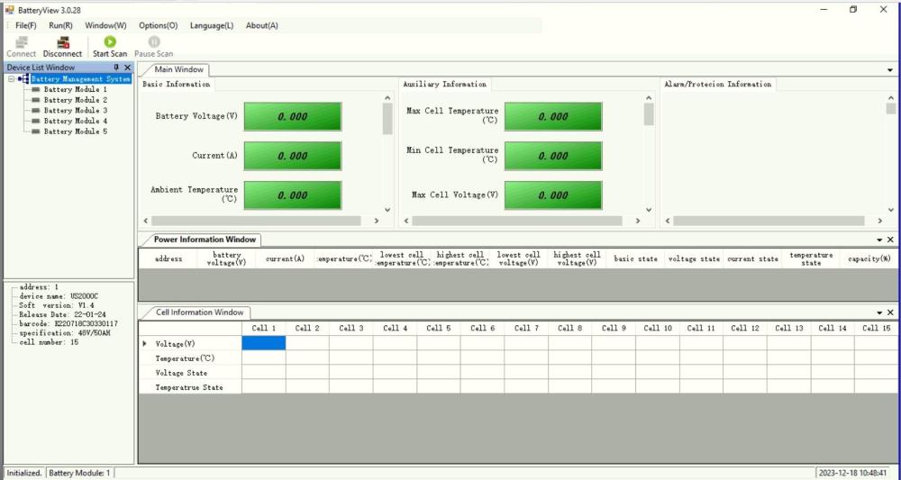
Hi Onze Finca, I have not tried with raspberry, but I can tell you that I have a micro-PC with both inverter and pylontechs connected at the same time. The usb port of the inverter (Axpert King 5kw) is connected to the PC and also the console interface from master pylontech is connected to another usb in the PC. I bought this cable from Aliexpress cause I had good references from members from another forum and it works perfectly: Cable de comunicación para consola de batería de litio US2000C US3000C US5000, Cable de depuración Serie USB prolífico RS232 a RJ45 8P8C - AliExpress You can monitor and debug pylontechs using batteryview software.

-
It is really worrying having 125kg of lithium at home. In my case, there is a smoke detector and the whole system is installed in a concrete basement room, isolated from the house by 2 FD-120 doors. If the smoke detector triggers, the only thing I would do is ensuring the doors are shut before running away and calling fire brigade 😂
-
I cannot agree with your proposals. I think you are mixing parameters. Question #1: What voltage to protect the appliances? None of them will notice any difference at 230 or 240 as they are designed to work at both voltages. Question #2: At what voltage will they use less power? It depends on the type of appliance. A resistive load will use less power at 230V than at 240V as stated by Ohm’s law. Every inverter/rectifiying/electronic controlled type load will use exactly the same power as they transform mains power into dc power directly. The product voltage x current will usually remain the same. 240V = less current. In any case, it is only 4% difference.
-
Can you check the coments on the parameters above and share firmware version U1 as @Coulomb requested? You should be able to see the firmware versions on inverter screen.
-
I mean that you enter in configuration menu of the inverter, take note of the values for each parameter and post them in here. This is to understand what working modes/parameters are set on the inverter.
-
Can you read and share the config parameters of the inverter?
-
Could it maybe be warning 69 and not error 61? Kings used to show warning 69 on some firmware versions if the battery is fully charged and the inverter still tries to push charge into it. Are the batteries properly chained and configured? It is very strange that they show different voltages. There are some dip-switches that you need to configure to set master and slave batteries. Dip-4 off for master and dip-3 off for slave. I cannot see it clearly on the video, but they all seem to be on for both batteries. It is also necessary to configure communications on the battery to match the Axpert King protocol as described in the user manual.
-
What is the switching-over time of your inverter? There are fast switching models (Zero transfer time) to avoid that issue with computers, ATM machines, etc...
-
In such cases I always calculate how much I saved by doing DIY and then realize that it is not so painful paying for a new part (BMS) because you still save money.
-
There are formulas to calculate the force that wind will produce on the pannels. Once you know the force in kg produced by the wind, just add the necessary ballast. As an example: Calculation of the force for one typical 550w panel (2,23x1,13m @ 45degree tilt) Calculation of the effective surface that pannel opposes to wind: Surface= panel area x sen α = 2,23 x 1,13 x 0,707 = 1,78 m2 The force that the wind exerts on the obstacle surface of the solar panels is given in the form of pressure. At about 130km/h, the pressure exerted by the wind on a surface perpendicular to its direction is about 79Kg/m2. Now, part of this force that is exerted on the solar panels is lost when it slides across the surface of the modules since they are not completely perpendicular to the wind. For this reason, the total force exerted on the panels can be decomposed into two components with different directions; F1: its direction is parallel to the surface of the panel and does not exert force on it when the wind slides and F2: its direction is perpendicular to the surface of the panel and is what actually exerts the load on the support elements. The value of F2 is given by the tilt angle of the structure: F2= F x sin α = 79 kg/m2 x sin45 = 55.85 kg/m2 (for 130km/h wind) Therefore, the force exerted by the wind on each panel is given by the formula: F = P x S = 55.85 Kg/m2 x 1.78 m2 = 99.42 Kg Conclusion: The force exerted by a backside wind of 130 km/h on a solar panel measuring 2.23 x 1.13 m installed at 45 degrees is 99.42 kg. Typical concrete density is 2400kg/m3. You just need to add enough ballast according to the number of installed pannels and their tilt angle. Worst case is the first row as the wind will be slightly deflected on 2nd 3rd and 4th. Keep in mind roof maximal load too!!
-
There's a lot of adaptors you can buy. The only difficult thing is finding the right combination of male-female. Here's an example: Maincore Adaptador de cable coaxial hembra a RCA macho adaptador de cable de antena coaxial TV RF : Amazon.es: Electrónica
-
Nice plasma...
-
Hello Julian. You need to get the right cable to connect inverter to batteries, standard ethernet is not ok. You also need to configure the dip switches on the batteries if you have more than one. Check the user manual of batteries and inverter.
-
As you system is a voltronic clone, try with watchpower app. You can install it on an old pc and monitor the inverter remotely. You can even change the parameters remotely. I have an axpert king, that is very similar to yours and I have been using watchpower for 2 years now. In addition to watchpower, I installed a smart meter/switch on the grid connection to monitor and isolate the inverter from the grid when solar production is enough to supply the house.
-
I do not understand why you refer to non periodical signals now. We are talking about sinewave produced by the inverter. Of course you can measure RMS parameters over a non repeating signal and, of course you will be obtaining non repeating RMS values on every analisys interval. The inverter is called to provide the full instant peak power on every wave period unless you trim the peaks of the wave with the triac. We agree on that. I am still wondering why we keep discussing this. Additionally, the rating of the inverter is expressed in RMS Watts and/or VA. No one cares about the peak power of the wave. I keep talking about energy because there is no way to derate the geyser unless you replace its heating element. If the heater is rated 3Kw at 220Vac 50Hz it will always use 3kw at 220Vac. Nominal instant power will always be 3Kw, no matter what you do. The thing is that you keep mixing power and energy usage. I do not care what the nominal power of the heating element is, but care how much energy it draws every second, minute, hour or day, which in the end, is my limitation cause I do not want to use too much of my PV production on it. To reduce the energy the heater takes I can use several options like phase control, on-off thermostat, capacitors to increase reactance or even pure resistors, as somebody also mentioned. Each method will have pros and cons. None of them are perfect. Some will produce wave shape variation, some will change PF, some will dissipate a lot of energy as heat. Some people prefer capacitors and I prefer a triac for a pure resistive load. If we do not agree, that's life.
-
Please, can you elaborate a bit more what is the frequency of a slope? What is the definiton of frequency?
-
I fully agree about harmonics on inductive loads, which is not the case for a purely resistive heating element mounted on a geyser. By definition, any inductive element will store energy in form of magnetic field when connected to a voltage source and will send back that energy in form of an opposite sign voltage to the one that charged it when disconnected. That is why flyback diodes are mounted on relay coils or wherever that opposite sign voltage can be generated by an inductor. Unfortunately, we cannot use flyback diodes in AC and commuting of big inductive loads is one of the main harmonics and noise generators on the distribution grid. It is still possible to use some snubber circuits in AC to reduce some ringing and spikes. I highly recommend reading some literature on how & why harmonics are generated on AC systems. Harmonics (eaton.com) Harmonic sources | What causes harmonics (eaton.com) In addition I would like to point out that PF lower than 1 is the main reason for having increased currents on ditribution lines. A triac based system is not able to increase any voltage by definition when connected to a resistive element cause the resistive element is not able to store energy in any form. I still repect that you personally prefer other control systems.


