


Brian_SA
WD POWER HYDRO ELECTRIC
-
Joined
-
Last visited
Everything posted by Brian_SA
-
Hi @alec_s If you disconnect the AC out from the inverter and just have the AC in and Batteries connected does it still happen? Meaning if it does, that excludes all your AC output connections and the problem lies on either AC in side or the inverter. Also, there is a "grounding" testing setting in the solar power app for the inverter if I remember correctly? Maybe changing this setting could help??
-
We use an ESP32! All the rest is a trade secret!😆
-
We use the PID control to feed the power through to the inverter once we have the voltage stable on the ballast load. We control on voltage and ensure once the voltage is rectified we don't overshoot the max MPPT rating.
-
Tim, your statements are false and i disagree with you. I am a Hydro Engineer based in south africa. Efficiencies add up through a system by multiplying each one together. Let me give you an example from our hydros we supply: Overall efficiency = Turbine x Generator x hydraulic(pipeline) x electrical losses(inverter, rectification etc.) Typical calc: Turbine at 90% x Generator at 90% x Hydraulic line at 95% x Electrical losses 90% Therefore overall efficiency is 0.9*0.9*0.95*0.9= 69%
-
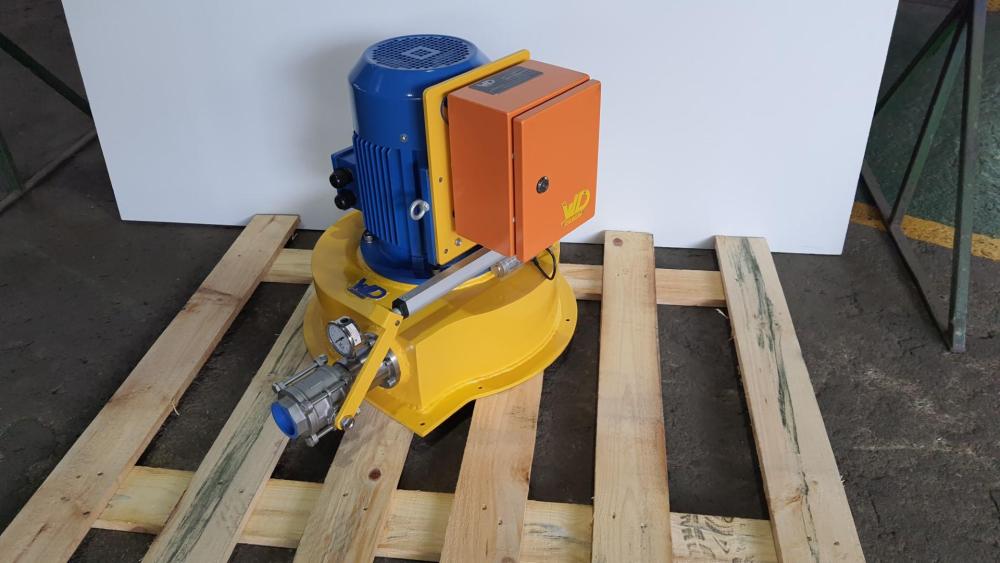
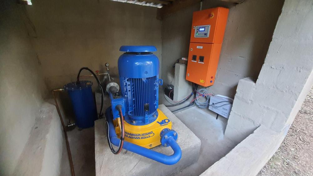
we do, feel free to DM me. WD Power... locally manufactured hydro units.
-
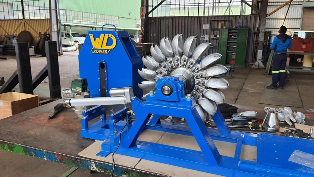
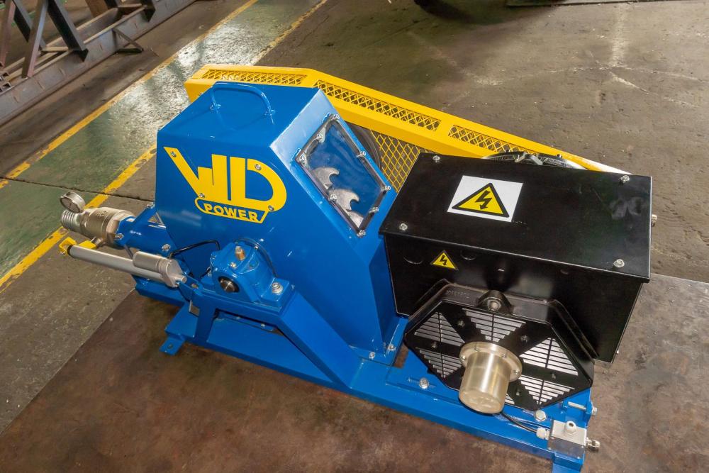
Hi Cassie, this can be done. but you need a special PID controller for the setup. The best way is to tie into the mppt dirctly after rectification. the volatges do go high and i think that the axpert have a low voltage mppt. it is tricky but can be done.see my above post of our micro hydro's we have done this with before. awesome small machines. Im not sure of the flow he has, but at 150m it will be a pelton turbine he will need to install.
-
see some of our micro turbines. we have built a special controller to tap into any inverter. the inverter basically thinks its a 24hr solar panel.
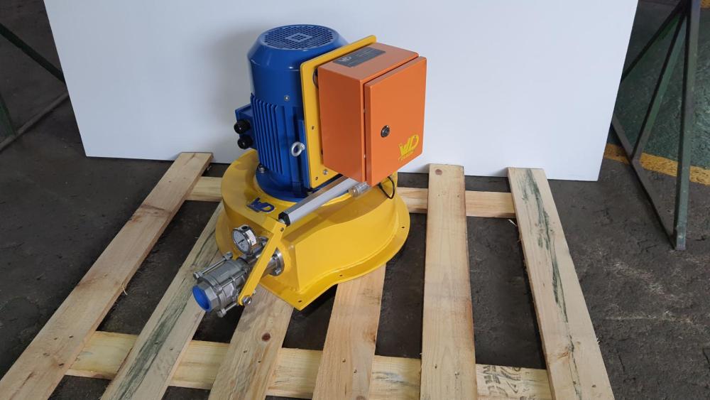
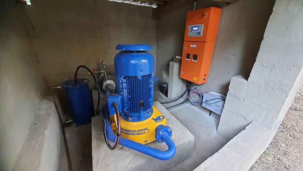
-
@Cassiei have controllers that can do this sort of thing. we supply micro hydro turbine to the sa market
-
@Tsa I am using solar assistant software on a Raspberry Pi unit. Yes, all the battery info is displayed on the solar assistant software app.
-
Hi All I know this is an old thread, but was wondering if you can solve a dilemma im having with the Narada batteries. I have noticed that the narada batteries are not holding a constant voltage during the SOC cycle and actually start at the set voltage and drop to around 42v at the end of their cycle. Is this common with these batteries. Im helping my friend that has this battery, we are monitoring through solar assistant, the battery code is 45NPFC200, very strange as i only find data sheets for 48NPFC200, not 45?? His is linked to a growatt 5000es inverter. Even on the 48NPFC200 data sheet they have tables showing output in hours and the voltage reduction to 42v. I myself have dyness batteries and see they dont ever drop voltage below 48v through a cycle. Was just wondering if you guys are experiencing this as well.
-
Hi @Johandup I control my geyser with a red pole wifi switch that can be bought from Takealot, works like a bomb: https://www.takealot.com/red-pole-energy-geyser-smart-wi-fi-switch-energy-monitor/PLID91347311?gclid=Cj0KCQjw48OaBhDWARIsAMd966DlKWq87z8_4O7dEOg49c4MU5uesKg2i6G8TgYPxc9eb1wJncpb9fUaAgenEALw_wcB&gclsrc=aw.ds It does not have a temp probe, but i suspect you could just add another sonoff at your geyser that will measure the temp and make them talk to each other by creating an automation or a scene? here is the sonoff: https://sonoff.tech/product/diy-smart-switch/th10-th16/ You should just be able to make a small housing on the geyser tank and pratley stick it on. Its crude, but should work. i think i will be trying this soon enough. 😄
-
I agree with @Bobster., rather look for a new property that has something installed already you can build on, or is well positioned for a good solar setup, i.e. North Facing, possibly already has a generator bypass on the DB. To assembly and disassemble is not an option imo. Also, at 20kWh per day, which is similar to my consumption, a 5kW hybrid with 1x 3,5kWh Li batteries for some light at LS and a few PV panels should get you far, especially if the DB is done and so on in the new place you find. 100k should cover it.
-
Hi Steve and others on this thread. I decided to go have a peak at the ''grid relay'' function when in off-grid mode. The manual says as follows when using grid relay(off-grid mode I & II): PV power will provide power to the load first and then charge battery. Feed-in to the grid is not allowed under this mode. At the same time, the grid relay is connected in Inverter mode. That means the transfer time from inverter mode to battery mode will be less than 15ms. Besides, it will avoid overload fault because grid can supply load when connected load is over 5KW. the manual says as follows when not using grid relay(off-grid mode III): 1st Load, 2nd Battery PV power will provide power to load first and then charge battery. Feed-in to the grid is not allowed under this mode. The grid relay is NOT connected in Inverter mode. That means the transfer time from inverter mode to battery mode will be about 15ms. If connected load is over 5KW and grid is available, this inverter will allow grid to provide power to the loads and PV power to charge battery. Otherwise, this inverter will activate fault protection So it seems you will have the grid as backup in both cases, the only difference is the transfer time involved, if I understand correctly. If you want the transfer time to be less than the 15ms, you will have to accept that the grid will always be connected and pulling around 70watts of power in my case and oddly supply the load fluctuations in power at short bursts. As for my setup, I have no problem with the grid relay not being connected, this allows my grid to have 0 power consumption from the inverter line as long as my batteries are sufficient and no overload occurs. It might be different for each individual here, especially if you export to the grid, which I have no experience in. Cheers!
-
Thanks Steve I have 2 units, will connect the second soon so I do not worry about overload, 10kW is plenty for me. I just seen a lot of people have been complaining of the constant grid usage, so it's a good starting point to see if it works for you, if you rely on the grid constantly I suppose you have to live with the reference load from the grid. Another way I have read is to set the grid compensation power to the same as your inverter load, it balances it out to practically 0, but then you still have the fluctuations present when your loads vary all the time, but at a stable load it basically stays at 0. Thanks
-
Hi Guys I have infinisolar and had this headache...but finally solved it on my side. My inverter was constantly pulling 80watt from the grid and fluctuated a bit with loads, but the grid was always being used. What worked for me is to set the inverter in "Off Grid III" when the grid relay is not connected in inverter mode. You still have the grid to support you and to top up the battery when required. So you won't be without power in this mode, and you won't used the grid at all as long as your PV and battery can support you. Let me know if it works for you as well.
-
Hi @Scorp007 I have set my mppt lowest voltage to be more near the panel max efficiency voltage of 39v, total of 12 panels is 468v, so i set it at 430min and 700max, before, when I was pulling high load my voltage dropped to 350v, which is 29v per panel. My mppt was set between 250 and 800 previously. So I'm hoping this might make a difference. Will see if that makes a difference, will keep you guys posted. Thanks for all the help and advice.
-
Just checking if anyone got this question: Another question, could I have the MPPT operating voltage be set incorrectly? If i take a look at the panel spec the correct max power voltage is 39V, i currently operate at around 29V when pulling current as the voltage is at around 350v total from all 12 panels(mppt min and max set between 250 and 800)... If i set the MPPT to operate nearer to the 39V, so total 470V from all 12 panels( so set min at 400 and max at 600), would it not improve the situation?
-
@WannabeSolarSparky, thank you, really appreciate the suggestion. I have another west facing roof that i can house another 8 panels, going to do that over x-mas and just up my battery bank to 14kWh. should be enough to keep me going. I installed this system 2 months back and i can already see a huge saving in consumption, produced over 300kWh in june, so im happy so far, just like to tweak it a bit to get the best of what I got.
-
@Scorp007 ok i understand, makes sense...I assume the layout is also catching me more than i think... I know someone with 6x 350W panels that are north facing in PTA, and with my 12x panels i can only produce around 300 to 500 more watts than him on any given day... interesting. At this exact time of typing i am only producing 1880W and he is producing 1550W.
-
Hi @P1000, understand, but at 12noon lets say we should be close max, no true....as all panels are pretty much exposed? @Nexuss, yes, a very high Voltage MPPT, thought it would be better to run 1x string and have a high voltage and lower current.. @WannabeSolarSparky ok, i will try that, basically raise the top end of the panel with around a 100mm spacer or so? or the whole panel? Another question, could I have the MPPT operating voltage be set incorrectly? If i take a look at the panel spec the correct max power voltage is 39V, i currently operate at around 29V when pulling current as the voltage is at around 350v total from all 12 panels(mppt min and max set between 250 and 800)... If i set the MPPT to operate nearer to the 39V, so total 470V from all 12 panels( so set min at 400 and max at 600), would it not improve the situation?
-
Hi @brian1709 I have recently purchase and installed 12x of the 480w THESUNPAYS panels at my please and i'm not sure if my performance is as expected. I have all 12 in 1x series string giving me a OC Voltage of close to 550V, each panel i have tested at 45.7V OC and 6x together at 247.3V which all adds up to the correct OC Voltage. I dont seem to however be able to produce anywhere near the expected power output on these panels. the most i get on a got day is 2,8kW to 3kW max. Im not sure if there is a better installation sequence to use or what i can do? I was expecting peak performance to give me at least around just over 4kW. Any suggestions would be appreciated! I have a single infinisolar 5kW inverter and 2x 3.6kWh dyness batteries, and the 12x 480W panels connected in a single string. My panels are layed out as follows: 6x at a north east direction, 1x at true north, 2x at north west and 3x at a west facing direction, all on a single string as stated. I use solar assistant and have attached a few snaps of panel layout and i have added last 7 days of solar assistant data. Any ideas what i could be doing wrong, or if this is correct as is? Let me know if you guys need more info?
.thumb.jpg.d0a16e95f8af77815ff87239b748c55f.jpg)
.thumb.jpg.4b9353765a123389d743f5b669b35545.jpg)


-
Hi @Buldogspanneri am using a rs485 cable from the battery to the PI. basically ethernet, to rs485 into usb on the PI. Make sure that your master battery only has dip switch number 2 up and all the rest down. and for any other batteries, all the dip switches down. Let me know if you would like a photo or 2. This is basically what the dip switches are doing: Dip1 - nothing Dip2 - Select the Master unit (set to 1 for master, set to 0 cant communicate) Dip3 - RS485 Selection (0 gives RS485 Comms in my tests) Dip4 - BAUD rate selection, ON is CAN250K or 485: 115200, OFF is CAN500K or 485: 9600. (0 gives 9600 comms and 1 give 115200 comms)
-
Hi guys... got this working through solar assistant using the above info and the details are correct regarding the DIP switch configuration. They have some how swopped them around. I will try read the bms now through the inverter and let you know if i come right.
-
Hi guys, figured it out, thanks.
-
Hi Lee Mun How do you read the state of charge? Do you use monitoring software? Or just the led lighting? I'm using software to monitor my 2x dyness unit and I cannot get the monitoring correct to see the correct SOC values.... I am not sure how the dyness comms work... Thanks for any advice.





.jpg.c392ca5872f658052f723e0f3679efd7.jpg)
.jpg.1b52849f397ef8286bcea811a481d3cc.jpg)


