


sethmad
Members
-
Joined
-
Last visited
Everything posted by sethmad
-
it seems it really is a problem with Pylontech pouch cells because of overcharging. If you have a Voltronic/Axpert inverter, i would recommend to disconnect the communication cable and set inverter to USER mode, then set a lower charging current and charge voltage at 3.4V or 3.45V * cell number. (51V for 15S) That should protect from cell overcharging. Also, it seems that pylontech balancer si weak... does anybody know how many amps are used for balancing?
-
is it safe to run the Main power supply without the RCD Snubber circuit? i got one inverter with failed UC3845... but the Q71 mosfet is not damaged. this is the first design that i see without RCD Snubber. Is this cost saving or something else?

-
SOLVED. there was another bad zenner in parallel with the good one. on this particular model, the MPPT IGBT's are powered by the same power supply.
-
Hello all, I've got this strange issue on a Voltronic type inverter. I've Replaced all IGBT's... quickly checked driver parts... seemed ok. Powered on... Boom ... 2 damaged IGBTS's again. After checking again I found one zenner 5V6 damaged, replaced it and decided to use coulomb's method (2 separate power sources, 12V and 20V) to test the IGBT gate drivers. All good, except the gate voltages for the 3 igbt's that are powered by same 20V power supply. In ON state i got 18V .... in OFF state I got only -1V instead of -5.6V. Further checking .... in unpowered state, with DMM on ZD2 in diode mode - I only have there 0.3V forward voltage instead of 0.7V as on other zenners. Also, when I check resistance of R10 (15K) - in one way (+...-) i get 15k.... when inverse the leads of DMM - I get around 8 kOhm. Desoldered R10 - checked and is OK - 15K - but I also measure 1K on the pads where R10 was soldered. Desoldered ACPL T350 - power pins 5 and 8 - same issue with that lower voltage drop on ZD2 desoldered TX7 - issue persists. PCB a little bit burnt near IGBT legs - check resistance and is no leakage. (see last photo) Any ideas what to check more? Im afraid to run it power it ON having only -1 [V] on 3x IGBT's gate.


-
great great work there! thank you for sharing! I have one inverter that is dead, no power on - I suspect something burned on auxiliary power supply.
-
Hello, I have an older EASUN Igrid SV4 inverter and I need to upgrade firmware from U1 56.00, U2 80.25 to U1 56.13, U2 80.41. What is the correct order to do this update? U1 then U2 or the other way around? I attached FW U1 56.13 in case somebody else needs this upgrade. 4165-08G RS232 FW Upgrade_28066_DSP INFINI V IV 5.6K 56.13.7z
-
after more inspection(repair) of other inverters, I noticed that the mainboard is actually from an offgrid inverter, this is why it is missing the U6. However, it works good and is reliable for 2 years now.
-
some info 1) SMG II 5.6KW 80A with MPPT 120 ~450V ->this one is similar with SMX2. But SMX II (2) is a SRNE clone/type, not Voltronic. It seems that EASUN is doing also SRNE type inverters and also Voltronic. The SMX2 Mainboard is the same as with Easun IGrid-VX-IV-5.6KW and can be paralled. The Main PCB is 4 layer and has more SMD parts on it. Seems to be a newer design since the SG3525 is not present anymore and the control is done directly from the MCU pins using drivers for the mosfets. 2) iGrid 5.6KW 100A with MPPT 120 ~450V - i suppose this is the SV4 model which is very similar with the SV2 but different display screen. later SV4s also do not have SG3525. SMX2: https://www.easunenergy.com/product/230vac-6kw-solar-inverter-48v-pure-sine-wave-mppt-80a-high-pv-input-voltage-500vdc-wifi-off-grid-solar-inverter/ VX-IV https://www.easunenergy.com/product/new-5-6kw-450vdc-pv-100a-hybrid-solar-inverter-230v-48v-pure-sine-mppt-parallelable-inverter/

-
@Coulomb could you please point out where to find more info on this missing capacitor? I have an older EASUN SV4 which has problems with the color display... garbage data is displayed on the screen but could not find the rootcause.
-
I recommend that you try SolarAssitant. You set the inverter to USE battery and the SolarAssitant communicates with your battery and with the inverter and can control the stop of charge. It runs on a raspberry PI and it's worth the money. Easun has many bugs in the battery LIB protocol.
-
I encountered this particular defect on 3 inverters (all EASUN SV IV) - The PCB is exactly as in your pictures, with that thin trace connecting Neutral to Earth in battery mode. Sometime burns like that.... sometimes is more messy (burned hole in the PCB) possible rootcause for 1st inverter: User had some faulty wires on PV panels. Panels were mounted on metal support, when there was a rain outside there was current flowing from panels to earth. I think that reverse current somehow destroyed the thin wire. Possible rootcause for 2nd inverter: User was trying to feed power to another Inverter (OUTBACK type). I measured 30V AC, 50Hz on Generator Input of the OUTBACK inverter (I dont know this inverter so I did not investigate more). There was also a problem with an AC cable he was using - there was short circuit in the cable and the cable heated up. (probably L was shorted to Earth in the cable) - he had no Differential protection mounted and no fuse on AC output. Later edit: Now I wonder if that thin wire is a mistake or is intentionally done like this. On EASUN SV2 I have not seen it. @Coulomb you were mentioning Fault 53 in a previous post. Could you please explain what conditions are checked for this fault? (Long story short: I started repairing an Easun SV IV inverter - display board was defective, changed uC, reflashed, OK, replaced burned mosfets, replaced IGBTs, replaced burn resistors, one optocupler+diodes. Now I powered ON and is stuck at Fault 53. I measured 360V on the BUS, so I suppose the DC-DC converter is working OK. No AC out but I've seen 50Hz displayed for a second on the main display. Any ideas what to check next?
-
@mihaigsm2003 thank you very much for the valuable information. I successfully recovered an LCD communication board. Resoldering the chip was the most challenging part! BTW: did you have any success in replacing the uC on the controller board? I understood is protected by password. what tools would you use in order to reflash? (what jtag interface is cost effective?) @Coulomb thank you very much for organizing all this valuable info in a separate post! Do you have by any chance a schematic diagram for the main controller board (the one with the DSP)? (for example the one that has 3x 16 pin connectors) I just want to see how all opamps and all other components are organised there.
-
If that voltage regulator (3.3v) heats up, the microcontroller has short circuit on the power lines. It can be replaced (if you have the necessary tools and skills). I've done it on 2 boards and i was successful. the STM chip needs to be reprogrammed, there is a separate thread on how you can do that.
-
Thanks a lot! @Coulomb Does anybody have a quick guess on what could go wrong if someone accidentally swaps the PV input wires(reverse polarity on PV input)? This seem to be the main cause of the defect. Unfortunately I have 2 boards with exactly the same behavior. This is why I firstly thought it's a software issue. (very big coincidence as these boards came from different persons) Board1 - Had the big 500V capacitors exploaded - I replaced them and now seems to be working fine - except the MPPT part. Board2- had defect IGBTs on DC-AC part, replaced them and seems to be working fine - except the MPPT part. Owner reported that this behavior appeared only after accidentally reversed polarity of PV inputs. All power IGBTs and power diode seems to be OK. Mcu reports no error - it just tries to lock the MPPT but voltage drops to 350V to 40V and then restarts. Will check more next week(I hope I can get a good board so I can do cross measurements also). Any hints would be greatly appreciated! I attached some photos. MPPT is included on the mainboard on this model.
_MPPT.thumb.jpg.c3cbad8175d6c14f6ac661eba7a826db.jpg)

_specs.thumb.jpeg.70aeed120ac52f4401182faf8f4a250b.jpeg)
-
@BritishRacingGreen I was reading for 2 hours about your journey into repairing different inverters. This one particular defect I am experiencing also on a Easun SMX2 inverter. MPPT does not function as expected - more or less the same behaviour as you described. What was the conclusion you found ? The inverter I received had burnt IGBTs on DC-AC side, replaced them and seems to be working OK now. However, the owner said that this MPPT error was present before it finally died. Someone probably connected PV input reversed. I checked diode and IGBTs on MPPT controller - they are good...
-
So it blew out the IGBTs when you put more than 3KW export to grid? That is good to know. Have you repaired it yourself?
-
I did some more research and it seems that they are produced by https://www.nextpowersolar.com/ They are similar to voltronic but seems to be another design and production team. What do you guys think about this?
-
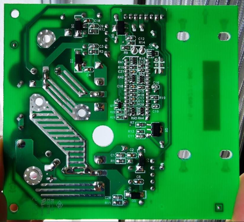
any chance to find a schematic for this small PCB board?
-
Seems i found an answer in this thread: https://powerforum.co.za/topic/4170-axpert-repair/?do=findComment&comment=183455 "This board basically houses some SCRs which implement the UPS AC input range setting. It allows the inverter to switch to or from battery mode in roughly 10 ms, as opposed to about 20 ms without it. That's not something you'd typically notice unless you have sensitive equipment and/or are looking / listening for it." @Coulomb "Edit: another possibility: I believe that that PCB is only needed to get the fast transfer when using the faster UPS "input voltage range". I've often wondered if you can choose APL instead for setting 03 and just remove that board My understanding is that the board uses TRIACs or similar to reduce the transfer time from battery to/from line mode (less delay connecting AC-out to/from AC-in and inverter out)." @Coulomb what do you think, is it safe to run the inverter without this board if using in APL mode and not UPS mode (in setting no 03)
-
Hello all, I have an inverter that after a local storm got this board damaged. If I unplug the connector to this board, the inverter works as it should, no errors displayed, charges batteries, PV voltage is detected. Does somebody know when is this board used by the inverter? In parallel mode only or only when feeding power to the grid? It has 4 SCRs of type BT155W-1200T. If the board is plugged in, the inverter does not power on. Also, did anybody reverse the schematic for this board already? Thanks in advance.


-
@Coulomb I am not sure if this particular inverter was reflashed by the owner or not. It is an older inverter, 3 or 4 years old as far as i can tell. This is how I received it for repairs - it had short circuit on PV input. ZVS diodes were defective. Probably someone connected it to a 400V DC PV string and max supported is 145V DC. I tried connecting to it via Solar Assistant and the SN read is 55355535...., so probably a clone. This is how the label looks like. Housing is of Gray color

-
I recently repaired an offgrid inverter (Isolar SML 5K-Parallel, probably EASUN) - equivalent to Axpert Offgrid as it had already a patched FW loaded (LC1 72.70C with AussieView. I was curious about consumption from Grid in bypass mode and no Load connected - same values as for Infinisolar V2 - 2 Amps but only 50W Active power. So a lot of reactive Power. I wonder if Growatt inverters are the same issue.
-
Hello @Coulomb, could you be more specific what is exactly this "premature float bug"? Is is linked to charging batteries? I use LifePO4 batteries and I have set both float and charge to same voltage, so I'm probably not affected by this bug. On which versions of the Infinisolar V2 is this present, how can i test? I have seen inverters with following SW versions: 52.20, 52.29, 56.60 Also another question: Would it be possible to limit the energy fed to grid? I have 2 Infinisolar V2 running in parallel and I want to limit the energy fed to grid to 2.5 or 3KW on each inverter. Otherwise my safety switches (I use 32A, 2P automatic fuse / MCB) and it gets hot on 7KW (60 degrees celsius)
-
Hello Coulomb, could you be more specific what is exactly this "premature float bug" ? On which versions of the Infinisolar V2 is present? I have seen inverters with following SW versions: 52.20, 52.29, 56.60 Also another question: Would it be possible to limit the energy feed to grid? I have 2 Infinisolar V2 running in parallel and I want to limit the energy fed to grid to 2.5 or 3KW on each inverter.
-
did you find the software? I have same inverter with SW 52.20 and it does not "continuously charge" from AC IN.


_MPPT.jpg.f370b783c01e8591d1b343f43ce96658.jpg)

_specs.jpeg.28177c286b70adb890f1c2b3362d35ea.jpeg)


