P1000
Members
-
Joined
-
Last visited
Everything posted by P1000
-
This is not always the case - (at least with some firmware versions) it will take the lower value of the two.
-
That luxpower linked has fans - look at the datasheet. AFAIK, the LXP variant is fanless - but also more expensive. Personally I would choose a fanless model (and consider mounting it inside). In an enclosed space, something with a fan will be better, but it will still impact cooling ability.
-
Option A is correct, but you still need to account for efficiency losses. Sunsynk does not give the efficiency of it's battery to AC conversion and if they did it would be load dependent. I would work on between 90 and 95% + 70W self-use. So option A is the correct method, but option B's answer is closer. Keep in mind that you are unlikely to find a battery that actually allows you to go down to 0% SoC (those that do are usually 10% overspec).
-
Power factor won't affect power from the battery that much, it might increase losses, but the battery only supplies the real power part.
-
If it worked before, first check shadows and angle of the sun. MC4 connectors might also be a candidate - depending on how your strings are connected. Measuring only voltage from panels does not really eliminate any possible causes.
-
Yes, those panels usually don't spend a lot of time above 12A, and there is very little area under the curve of the difference. Getting just-about 4kW from 8 of those 550W panels for that many hours is actually quite impressive. That said, swapping MPPTs costs nothing and would be a worthwhile experiment IMO.
-
What happens when the load is more?
-
Personally I'm partial to the Metcal or Thermaltronics stuff, but that's probably not very good advice for this sort of work (Perhaps the GT120 is a good choice, but it's a bit overpriced for this IMHO). Also note that wattage does not mean much if it can't efficiently transfer energy to the joint, this is where Metcal/Thermaltronics really shine, in many cases you can do the same work with half the power rating just because of the way it works. Perhaps something like this, but with genuine JBC cartridges?
-
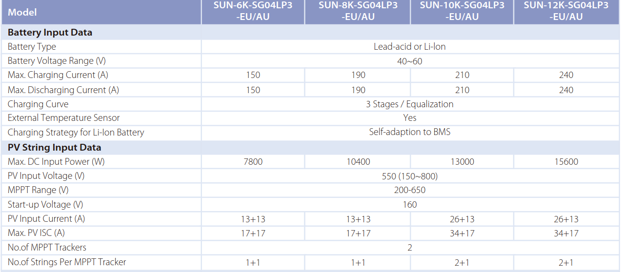
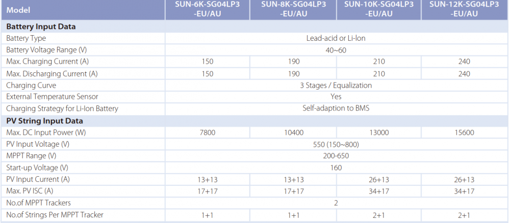
Looks like the max panel current you can put on it that the MPPT will still manage to control. The MPPT will still limit to 26A+13A (according to the Deye brochure attached). I have never seen Isc ratings in Sunsynk manuals - they really should put them in there.
-
In some cases with some boards with heavy copper fills, I have previously resorted to using a soldering iron from both sides, before trading one for a compressed air gun to blow out the solder. It works really well on stubborn vias, but be prepared for a cleanup. Having proper equipment is really worth the investment, though!
-
My suspicion is that the breaker was not actually rated at 600V DC. That is to say - it's not rated to break a load at 600V DC. To do that most breakers have a spring loaded mechanism in order to make the gap big enough, fast enough to quench the arc. (most likely also in combination with magnets to direct the arc away from the other contact - one of the reasons why DC breakers are usually polarized.)
-
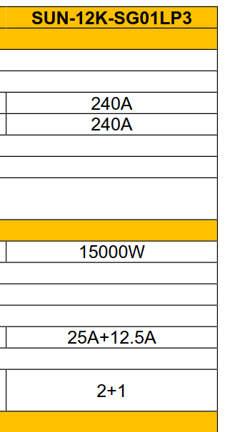
MPPT2 clips at 12A as can be seen from your graphs. MPPT1 is rated at 25A. Swap the MPPTs and you should get better overall yield. I'm not sure why it is clipping at 12A, the datasheet states 12.5A, but they often change things if they don't work in the field...
-
Yes, I just thought I should clarify. From your post it could be interpreted as just adding a CT to any inverter will work.
-
Looks like the same one that comes in the Hubble, BSL, FreedomWon eTower and others. The dipswitches aren't the same for all those, as the firmware is different, but start by reading the manuals for those.
-
A CT in itself does nothing to the power flow. It just tells the inverter how much current is flowing - the inverter does the rest. But essentially you need to be able to measure current and voltage to be able to prevent export, so in that sense a CT one of the options you have for that (and also the most convenient). Anti-islanding is something completely different, but you also need to measure current and voltage to detect it.
-
Except if the coil is already energized, the contacts closed, and grid fails, you could still be powering the relay coil from the inverter through the contacts. There is a specialized anti-islanding device that is a bit more complicated for this sort of application: https://www.victronenergy.com/accessories/ziehl-voltage-frequency-sensitive-relay-ufr1001e Aside from that, inverters that comply to IEC 62109 (or perhaps VDE-AR-N-4105, not sure) and NRS097 should have ample anti-islanding redundancy that you don't need something like this.
-
I think it only applies to inverters with 2 MPPTs, but 3 sets of MC4 inputs. I have not seen a 12kW with a different configuration, although I don't have a big sample size.
-
Ok, that's strange, it also has only 3 strings input. In this case I think it might be a limitation of the MC4 connector and is most likely enforced by the MPPT.
-
One MMPT does 25A, the other only 12.5A. So your config will work fine for the 25A MPPT, and run at a heavy loss on the other.

-
2p10s will lose so much power on the one MPPT that is only 12.5A. The post above yours is a much better approach. I also think the F55 is indeed PV overvoltage.
-
20 of those panels in series per string? If so, then that's too many.
-
That is still a low voltage battery. HV batteries are 200V+.
-
A PC can run on DC, since the first thing it does is rectify the incoming AC. Some (older/cheaper) power supplies with power factor correction don't like the modified sine . Since most UPSs designed for PCs are modified sine, you have a very good chance of it being fine.
-
That is only for the PV to AC in grid-tied operation, mostly because it is a requirement in some countries to meet a certain threshold. The battery to AC will have lower efficiency, because of the low voltage and physics (and is why many of the inverter manufacturers are moving to HV batteries). The efficiency will also vary greatly with power level. To determine the actual efficiency, you would require some specialized equipment, relying on what the inverter reports is not a great strategy for accurate answers, but it's possible that the inverter reports actual values.
-
It looks like the pinout written on the inverter differs from what is in the manual: Also see this thread: You can get a cable here: https://www.inverter-warehouse.co.za/products/luxpower-to-pylontech-coms-cable Also note: try not to mix pairs, so use the blue pair, and change the pins on the other end (don't mix green/blue like in the linked thread).