


Coulomb
Members+
-
Joined
-
Last visited
Everything posted by Coulomb
-
I note that support for PIP-GK and PIP-MK (Axpert VM III, and the Axpert King) have been quietly dropped. There is a Pylontech-specific PDF on how to set up your machine without proper BMS communication, but that seems to be it. I see nothing on the actual Voltronic Power web site; for whatever reason the MPP Solar web site seems more up to date (most of the time). This is despite Power Punk's appreciated post about "completed development" for the Infini series. This seems to be for brand new machines; older machines and existing stock seem to miss out, sadly. For new Infinis, it seems very simple: buy the modbus card, insert it, plug in the supplied cable, and power up the battery first. Nothing more to do, and you get accurate SOC readings on the inverter. [ Edit April 2019: It seems that recent 5 kVA models of the VM III do talk directly to the Pylontechs after all. Maybe the King will follow soon. ]
-
Duh, yes I do, sorry. Corrected now. I don't think so. They track the voltage and current all the time (e.g. zero crossing interrupts), so as to synchronise AC in and AC out. That's needed for paralleling, as well as switching somewhere near the zero crossings of load current, though I admit that since APL mode takes a full 20 ms cycle (at 50 Hz), there doesn't seem much point. It's possible that the "value line" models (VM series) don't bother synchronising AC in and AC out. In fact, I've just checked, and the firmware for a VM III has a much simpler SynchroZeroCrossInterrupt() interrupt handler, although LineZeroCrossInterrupt() is essentially the same.
-
On this very forum: https://powerforum.co.za/files/file/14-pip-hs_ms_4-5kva_new_service_manual_201506a/
-
Sadly, you have to ask for it from your supplier. I'm not aware of any other source for it. Of course, it came with your inverter from the factory, but you can quite rightly claim that it was very confusing what you were supposed to do to use your existing investment with your new inverter. Hopefully, that (along with several emails with photos of labels) should be enough to get a firmware update file for it.
-
-
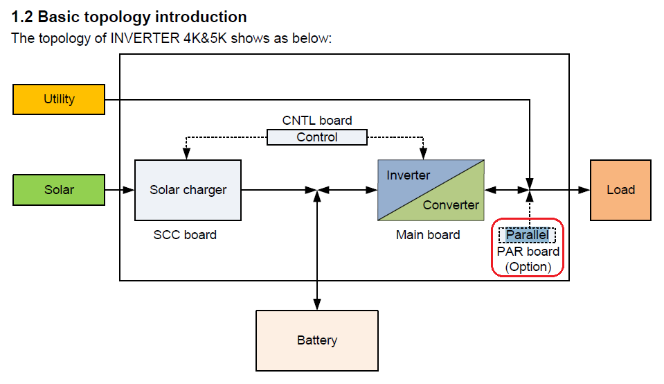
I don't! But somehow, it doesn't stop me from guessing. I've long suspected that this card is to do with the faster transfer when you select AC Input Voltage Range (setting / parameter 03) to UPS, rather than the default APL (APpLiance). I never did get to the bottom of what the firmware does with this setting; it's never been a priority. I suspect that with the card removed, if you change setting 03 to UPS (edit: was APL), then there will be an error, or it just won't change over as fast as it would have with a working card. That card is referred to as a "parallel power board" in some of the service manuals. This suggests paralleling of machines, of course, but that makes no sense. If it is for paralleling the relays with Triacs or whatever they are, this makes more sense.
-
I think you need to get him/her back. What you see is pretty much what I'd expect if the connection from master to slave on the AC outputs wasn't connecting somehow. It could be as simple as a terminal not screwed tight. If you're not familiar with electrical work, don't attempt to fix it yourself. I'm not hearing anything about breakers at the AC inputs or outputs. Those should be there (three total; the AC inputs can share a higher current breaker). A photo of the wiring might show something obvious. I agree with others that the most important test is to switch off the slave to see if the master can power the load on its own. There could be something with the current sharing cables, as others have also mentioned. You could be justifiably cranky about the installation not being properly tested.
-
I assume you mean 44 VA. It sounds like your master isn't paralleled with the slave at all, and isn't providing any of the load. Check your AC output wiring and breakers.
-
This will be a continuing problem. That would have been a 75.XX. You can't mix single and multiple MPPT models. It's not just LA batteries; all batteries. As far as I know, no Voltronic Power factory firmware has the charge bugs fixed. Interesting. Did you try 72.70c in the older inverter, and leaving factory 74.30 in the new? I believe that's how it's supposed to work. But if you want the LiFePO₄ version, you'll have to update both anyway. Well done. I'm actually slightly surprised you were able to update the firmware on the new inverter. I hope you realise that you now have two 4 kW inverters, not a 4 kW and a 5 kW. Not a bug, feature! The font changes are meant to me more readable. RTFM (Read The Fine Manual) here. No, it won't; it's older firmware. What settings are now missing? Then I believe you'll have needed to have downgraded your 5 kW to a 4 kW anyway. Don't forget to change to the LFP version of the patched firmware at that point.
-
This one at least explains the QPIGS fields in detail. I hope it matches your inverter. The Infinis seem to have a lot of protocol variations. Infini-Solar 3kW protocol.pdf
-
I might add that while third party insulation monitors are expensive, of the same order as an Axpert inverter, I don't think it would cost much to add to an inverter. But the cost is likely in proving that the system is adequate for the task. Fried customers because a cheap relay failed open circuit is a bad look.
-
That's where a machine tests regularly that both sides of the PV array are floating electrically, i.e. there is no leakage to earth. This is a necessity in many jurisdictions, if the array voltage is hazardous. Extra Low Voltage. The hazardous voltage line has to be drawn somewhere, and it's usually called at 120 volts of ripple free DC, or 50 VAC. There seems to be a push towards even lower voltages, like 60 VDC. Lower than this is called extra low voltage, and while it can hurt a human with dry skin, it's unlikely to kill. Over extra low voltage, it becomes low voltage, which is considered lethal. House power points are LV. It is possible to be rescued from contact with LV, and electricians train for this. There is medium and high voltage after that. So safely protocols vary depending on the risk. For low voltage (lethal) solar panels, it's possible to make say a roof silently lethal. Hence the requirement in many jurisdictions for insulation monitoring, and regulations about how persistent the alarm has to be, etc. And if it keeps the government bureaucracy busy, so much the better (edit: from their point of view). But there is a legitimate safety concern too.
-
It's a Voltronic Power Axpert MKS II, also known as a PIP-5048MG. No use in Australia or elsewhere with strict rules, since there is no insulation monitoring, and the panels are higher than ELV voltage. Very convenient to wire the panels if you can get away with it. I wonder how these will fare post February though; in a sense they'll be "even more not on the list" than other Axperts, since they won't be on the list, and won't even be able to get there because of their design.
-
Heh, total cotton wool babies I believe that the 3615 stamp implies manufacture in the 36th week of 2015. So about September 2015, I think.
-
I don't, but I can guess. The "Zero transfer time" claim seems to indicate that, as you speculated, all load power goes through the IGBTs of the inverter. The web page actually mentions servers and Auto Teller Machines as the target market. These models are parallelable, so I suppose if you have a large, unpredictable load (like a household), you just have to have enough machines paralleled to cope with the highest expected load. So I think that these don't even have transfer relays at all. There must be a power factor corrected rectifier to turn mains AC into DC for the "power bus". I'd guess that there has to be a boost stage as well, since at any time the mains voltage might be lower than 230 V, and besides you always need some headroom for IGBT voltage drops and the like. @Gnome posted some internal pictures and speculations. I think we decided that there were wires to a boost inductor in the corner.
-
@vladgon, you'll be forced to write some assembly language code, so you'll need an IDE that understands HCS08 (I don't know of a free one, but maybe you can use a limited code size version of IAR). You'll have to know at least a few instructions, so look at for example this manual : https://www.nxp.com/docs/en/data-sheet/MC9S08AC60.pdf If you're old enough, you might understand this comment : The HCS08 instruction set is 6800-like. Mostly you use just 4 registers: a (8 bit), h and x (often used together as a 16 bit register), and sp (16 bit stack pointer). This might give a little more of a flavour of what you're getting into 🤔
-
Ahem. All those problems were supposed to put you off. Perhaps you should attempt to obtain the firmware image as a first step. Though I guess the chip might only cost a few dollars. Good on you for your positive attitude.
-
Ah. Then I think your only option is a new main board. I certainly don't have a 9S08 bootloader, sorry. It would be nice if suppliers were able to provide a programmed new chip, but I think that's most unlikely. Edit : a final off the wall idea. You might be able to get a JTAG or other programmer for the 9S08s (sometimes called HCS08 family). The firmware might operate ok without a bootloader at all, or with a sort of null bootloader that merely passed through control to the main firmware, but the machine would never be able to firmware update without doing the JTAG or other programming again. But then you still need a main firmware for that model, so you'd have to either be very lucky and find a copy on the web, or get that from your supplier. And possibly massage it into whatever form the programmer needed. Maybe it will read the Motorola S file directly, if you're very lucky. Serious skillz would be advantageous.
-
Basically, no. [ Edit: yet, it was done! ] As Plonkster mentioned, you would need the boot loader [ Edit: which is not available ] [ Edit2: it seems that the bootloader isn't necessary for these machines, except of course to be able to update the firmware. ]. To load the loader, in addition to the non-existent bootloader, you need special hardware and software. It's not all that exotic, but it helps if you've worked with TMS320 JTAG before (actually, a 3K model might not even use a Texas Instruments TMS320 processor at all, which would bring it even further into unknown territory). So your only option is to buy a Control Card as a spare part from your supplier. Weber has done this, and so far it's been quite exasperating. It took months to get them to understand exactly what he wanted, send all the barcodes etc, wait [ Edit: I initially thought, for them to reprogram it (it has the serial number burned into EEPROM), but they seem to come with generic serial numbers ], and finally delivery. It came with an unusual firmware version, and I think he's still waiting for answers on how to proceed with getting the right firmware. Hopefully your experience will be better. Edit: you can read more about Weber's control card order in the last paragraph of this post.
-
That's weird. Maybe it isn't a very good inverter model, or the inverter has broken in such a way that it's essentially direct-on-line (non inverter) now. Both guesses seem unlikely to me. If the 4.5 kW is real, then it's not the inverter's fault (it's only capable of 2.4 kW continuous), and it's right to switch to line mode if available. I'd say your lead-acid battery at 2.5 years, which will have suffered from the charge bugs, isn't capable of staring the air conditioner motor any more, even with the inverter (in the aircon) helping to keep the load lowish. Perhaps another model of air conditioner that has a more suitable load profile would help. Or possibly it's lost some gas, and takes more power to start; I don't know if it works that way. So: perhaps an air conditioner service? Perhaps make sure that the battery is getting properly charged, and isn't prematurely going to float stage? If it does, use a high load to force it to bulk/absorb mode again, and do this till you're satisfied that the battery really is properly charged. Then it might be in a lower internal resistance state, and might be able to start the air conditioner.
-
Wow. I think you get the prize for the most spectacular component failure I agree with plonkster's identification. I have to say, I didn't recognise it until I followed his link.
-
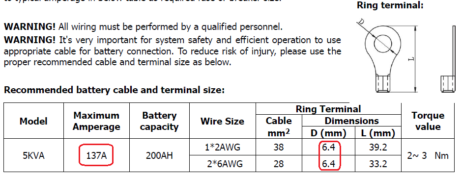
In the PIP-5048MG manual I happen to have downloaded (equivalent to the Axpert MKS II, 5 kW, 450 V MPPT), it specifies the lugs as follows: 6.4 mm seems to be the nominal hole diameter for an M6 lug. I use M6 lugs here, and though it's a bit of a hassle getting the lugs over the studs with 50 mm² cable, it does fit. I worry that using an M8 lug might reduce the contact area too much, possibly leading to heating of the connection. However, it would make getting the lug over the stud much easier. This is the same specification as for the 5 kVA / 4 kW models. A colleague uses M6 lugs in his PIP-5048 (5 kW model).
-
No, I don't believe that this is normal. You might find a short from AC out neutral to earth, which surprised me when I first encountered it. But upon reflection, this is expected in models with the neutral to earth relay contact.
-
Axperts will never admit that their measurements result in more reactive power than real power. [ Edit : I screwed that up. They'll never report more real power than apparent power. Please see Weber's post about 12 posts down.] So it might have measured say 117 VA and reported it as 114. All that means is that the LC filter on the output of the inverter is swamping the output with reactance, so the power factor with the low fridge-only load is near zero. It's not clear to me why the VA figure is different when AC is available. Maybe the bus voltage has to be a little higher and that affects the current to and from the filter. In any case, I don't think you can make meaningful predictions from this.
-
Those four black boxes (vaguely T-shaped) at the right of the photo are the four relays that make up the transfer switch. The relays connect AC in (Active and Neutral), inverter out, and load out. The neutral AC in relay is the one that becomes a changeover type in some models. On some brands of relay, you can see whether they are changeover or not by a sort of schematic on top of the relay; not the ones in the photo above, but as below. Block diagram: Actually, that's Weber's guess at the configuration with the changeover relay. From this post.


