


Coulomb
Members+
-
Joined
-
Last visited
Everything posted by Coulomb
-
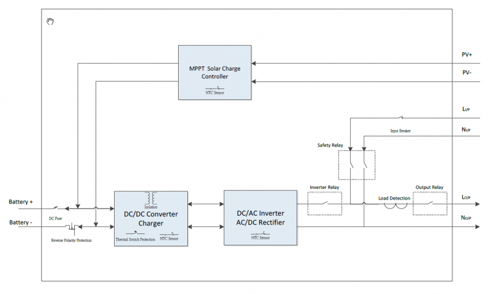
There are four relays on the Axpert, as per the attached diagram from one of the manuals. When AC charging (utility or generator), all four relays are on. So the inverter's "output" terminals are connected across the AC input. These are really input terminals when the inverter is configured in reverse. But like an AC motor controller in an electric vehicle, it is trivial to change the direction of power flow. In a vehicle, you can change from "motoring" (battery to motor load) or "regenerating" (motor/AC source to battery). The principle is the same whether the load is three phase or single phase. In my opinion, it is theoretically possible for the Axpert to push power into the AC "input". In fact, any inverter where the output can synchronised and connected to the mains can push power into the mains. It can't be avoided. If you want something that can't possibly push power to the mains, then you need a different architecture, like the 3 kVA models. See the second attached diagram. In this architecture, the inverter output is never connected to the mains. There is a completely separate charger for the purpose of charging the battery. A large charger becomes a significant cost, so why not use the inverter that is present anyway to do the charging? That seems to be the logic. So I have to respectfully disagree with @Gnome on this one; it's not physically impossible on the 5 kVA models to push power into the mains. Having said that, I've never seen the slightest suggestion that this ever actually happens. There may be "interlocks" in the software; that part of the firmware is very complex, and I haven't had a need to analyse it in detail. But whether there are or not, it's still "just software" and could theoretically go wrong and push power into the mains. The marketing of course suggests otherwise, but as far as I can tell, the attached diagrams show that it is possible.

-
Interesting; thanks for the data. Would it be possible to check one more thing? Can you check the power factor at the AC input of the Axpert when generator charging? Perhaps just a clamp current meter would do. Record the power factor or AC current into the Axpert near the point where the waveform starts distorting. The Axpert is using phase control to cause the inverter to draw power from the AC input to the battery. It needs to adjust the amplitude of the inverter output to control the power factor, or equivalently, to control the reactive power. If it's not doing a good job of adjusting the amplitude, the power factor can be very poor, and many generators won't like that. They might be heading towards their current limit way before they reach their rated power, and that could cause distortion of the waveform. When the waveform is distorted enough, the Axpert will find it hard to stay synchronised, and this would be why it drops the charge current. With utility charging, the mains will generally not be affected by poor power factor much, so the charge current doesn't drop. One weak data point: when the Axpert is powering loads and AC input is present, the inverter locks phase with the AC input. I believe that this is because it can perform a bypass transfer (utility replaces inverter for powering loads) much cleaner that way. But it makes no attempt to follow the amplitude of the AC input. This is a bit of a stretch now: perhaps it generally doesn't care much about the amplitude of the inverter output. Maybe they even leave it at 230 V all the time. Would it be possible to adjust someone's generator output to 230 V to see if they can get more charge current from their Axpert that way?
-
It occurs to me that if you have an inverter/charger of unknown own origin, and it has firmware claiming to be 72.60 or later (i.e. if you can scroll through the displayed data with up and down buttons, and come across one that starts with U1, and the other two groups of digits say "72" and "60" or "70" or any two digits greater or equal to "60" in that order (i.e. the 72 to the left of the other digits), then the following is a fairly sure-fired way of determining if you have a genuine Voltronic Power manuactured unit. It involves a command that I've mentioned in passing before. You need to hook up a comms program to the serial port (as far as I can tell, you can't use the USB port). See the instructions on the AEVA PIP-4048MS web page if necessary (in short, any comms program set to 2400-N-8-1, doesn't need to be Windows), and type this command: QFTY5200<return> where <return> means the enter or carriage return key. No CRC characters are required, and any attempt to enter them will cause the firmware to echo a (NAKss response (Negative AcKnowledge, with CRC of "ss"). If successful, you should see: VOLTRONIC POWER TECHNOLOGY CORP. I'm assuming that cloners will realise that leaving that there would be proof of a copyright violation, so they'd put "CLEVER CLONERS COMPANY" or any other string there to avoid being legal sitting ducks. Or just quietly not support that command, so you'd get the (NAKss response. This command is present in firmware versions 72.60 and later, and is not present in 72.40 or earlier. If there are versions between these two numbers, they may or may not have this command. If the command doesn't exist, you will get the (NAKss response. If you can't even find a U1 display page, then it's not a Voltronics Power Axpert. If it's a different design made to look like an Axpert to take advantage of their relatively good reputation, then the above will fail. If it's a really exact copy, then the above will pass, but hopefully it will also act like an Axpert in important respects, like being able to run updated official or patched Axpert firmware, and the settings should be the same, so that you can take advantage of the collective expertise on forums like this one. QFTY might stand for Query Firmware TYpe. I have no idea what the "5200" signifies. Presumably, it's designed so that people don't discover it accidentally. It seems too useful to leave it undocumented. If this is supposed to be a secret to catch cloners out, then I'm truly sorry. No-one benefits from copied hardware, including the copiers, I suspect. Voltronic, if you're listening, just put a slightly more subtle check into the next firmware, and I promise I won't reveal the next one. Oh, and please fix the charge bug; I'm sure you can figure it out by reverse engineering the patched firmware. I did try to email you about it.
-
I think that there must be at least PWM and MPPT models of these Prolines. It's not certain to me that any PWM models can use the patched firmware, or indeed official firmware with major revision numbers 72 or 52. It should be safe to use patched firmware on models with existing official firmware that has a major revision number of 72, i.e. 72.xx. Though I suppose it's possible that a clone manufacturer might deliberately make their hardware and firmware different from Voltronic Power's, just to avoid prosecution as a blatant copier, yet use a similar sounding firmware version, like 72.65 or even one of the commonly seen ones like 72.70.
-
While it's true to say that the patched firmware addresses several issues with the official firmware, there is nothing that addresses the generator issue. Certainly not directly, and I can't think of any way that it would help indirectly. OffgridQld, the AEVA forum user that started the topic over here, is running patched firmware. So by all means use the patched firmware if you need it (in my probably biased view, every Axpert user with solar panels needs it), but don't expect it to solve this particular issue. The patched firmware is better than official firmware 52.30, but only because it's based on 72.70, which is based on 72.40, which has a bug introduced between 52.02 and 52.30 reversed (fixed). Edit: it's gratifying to hear about successful installations of the patched firmware. Of course, it would be even better if the manufacturer listened and made the minor changes to their source code, so that all subsequently manufactured machines would benefit.
-
Yes, starting with this post: http://forums.aeva.asn.au/forum_posts.asp?TID=4332&PID=64717&title=pip4048ms-inverter#64717 It seems that charging at about 30 A is fine, but 60 A is not. Somewhere between these two, it will hiccup. I have a theory that it might be the first same inductor that gets hot (like 100°C), and may get hotter when utility charging. If so, one of the several thermal sensors would cause the power to back off, and this might explain the problem. But "no problem with grid power" ( @Hannes7212) would seem to disagree with that. It's good to know that 60 A total (two Axperts charging at 30 A each) is not a problem. (Thanks, @ebrsa). That eliminates some theories about what is going on.
-
I have had a report that the MOSFETs in some of the 24 V models aren't the same as in the 48 V models; they sometimes use Toshiba units with a higher RDSon. Possibly, whatever is available with the appropriate voltage rating. I believe that the capacitors can still be to blame, even if the MOSFETs are rated at 80 V. When a capacitor goes high impedance, the voltage spikes can be many times the supply voltage, easily exceeding 80 V when the supply is under 30 V.
-
It may come in the form of a .rar archive. I think Windows doesn't handle these by default; if so you'll need a third party app like 7-zip or Winzip to unpack it.
-
The firmware has to be the same version number exactly on all paralleled machines, and I don't think that this is possible wirh an MPPT and a PWM model. So: probably not.
-
I thought we were all going to brown (L1), black (L2), grey (L3) and light blue for neutral. Most mains cords here in Australia have used the brown and light blue for decades. The biggest hassle has been the USA using black for active and white for neutral, when so many countries use black for neutral. Australia uses white for an active, so that's completely opposite to the USA convention.
-
Chris, only a year late (only just noticed this post due to Barezzi liking one of mine from a year ago)... Solahahn in this post said: "This model" refers to the PIP-4048MSD, a dual MPPT version of the Axpert 5 kVA. So that's 7.2 kW nominal, an overclocking factor of 1.2:1. Ok, Solamahn is from Papua New Guinea (you asked for anyone in Oz), but he posts on the Australian forum. He has experience with dozens of installations, some of them quite large. OffgridQld has 8.2 kW of panels; it's not clear if all of that is connected to his single MPPT PIP-4048 inverter, but probably at least half of it is. I myself have 4.4 kW on a single MPPT model, though only 3.2 kW nominal of that is connected to the PV input of the inverter (the other 1200W goes via a Blue Sky Energy charge controller).
-
Right, But the possibly confusing case is three phase with 3 inverters. You need to use the "parallel communication cables" but not the current sharing cables. Here there is a master and two slaves, and they definitely need the parallel communication cables because they sure as hell need to be talking to each other to make sure that they get their phases right. So that you don't get two B phases, one A phase, and no C phase, for example. Plus, they need something to get the timing right, so they don't drift out of synchronisation, and are always 120° apart. The Parallel Guide is clear on the current sharing cables: So here we have three inverters working together, but none have their outputs paralleled. In fact, there is 400 V between any pair of outputs. But now add one more inverter for a total of four. You have to choose one phase to parallel your fourth inverter with. Now you have two inverters paralleled, and two not paralleled. The two that are paralleled (the two on the same phase) do need current sharing cables. The two that are not paralleled must not have current sharing cables. All four inverters are daisy chained together to talk to each other, and you'd better have the correct settings on the four inverters (e.g. 3P1, 3P2, 3P2, and 3P3 if paralleling on phase B ) so they know what to do. As I was typing this, I was wondering about the potentially random way that masters and slaves is assigned (in practice, one seems to become master like 95% of the time, but 95% is not 100%), does this guarantee that pumps will operate in the same direction every time you reconnect the battery? But of course, even though the first or second inverter might be the master at any time, the 3P1 setting in one inverter and 3P2 in the other will guarantee that master or slave, the one with 3P1 will always have the same phase relationship to the one with 3P2. It might be that today the 3P1 inverter is master, and tomorrow the 3P2 or 3P3 inverter will be master, but regardless, the one with the dark blue active (using South African or Australian standards) will always be phase C. (In Australia, the three phases are red, white, and dark blue; it looks like South Africa uses red, yellow, and dark blue.) Off topic: won't it be fun when they introduce the new international standards, and black will change from neutral to L2 active! What could possibly go wrong?
-
The cables that look like old EGA graphics card cables carry CAN bus messages; that's how the inverters agree on settings and I suspect they do a lot of synchronisation as well. The current sharing cables are a bit of a mystery to me, but certainly they carry signals not 230 V power. My guess is that they are connections to other inverters' current shunts. They probably need isolation. The signals are probably only tens of millivolts at full current. With respect to the question of where the voltage goes, consider two 12 V batteries in series. The total voltage will be 24 V or near 0 V, depending on which way they are connected. Where did the 24 V go in the second case? If you imagine switching one battery's polarity 100 times per second, you could see that a multimeter would read an average of 12 V. With AC, it turns out that you can get more than two polarities, you can get any phase angle between - 180° and +180°. It turns out that you can think of the AC voltages as vectors, i.e. things with magnitude (what an AC multimeter will read) and direction or angle. There are meters that can measure the angle between two AC quantities. The voltage and current drawn by an AC motor have a non-zero angle; that's why the power factor is less than one (typically about 0.8), and why volt-amps are more than watts. Where did the "missing" watts go? Same place as the 24 V from the anti-series batteries ; it's all about opposing voltages. Edit: Now imagine two mechanical switches changing the polarity of the batteries, and imagine that these are synchronised by a mechanical shaft, so they switch at exactly the same speed (same frequency). But you arrange the brushes or whatever so that while they open and close at the exact same 100 times per second, there can be a variable delay set by the position of the brushes. Now you can imagine seeing an average of -12 V to +12 V depending on the phase of the switches. AC is like that, except that instead of being +12 V or -12 V, the voltage changes smoothly over all values from about -18 V to +18 V. The average is zero, but another measure, the Root Mean Squared voltage, is 12 V, so that 12 V AC will light a bulb the same as a 12 V battery would. When you consider the instantaneous voltages of two 12 VAC sources in series, with the exact same frequency but different phases, it turns out you can measure anything from 0 VAC to 12 VAC depending on the phase difference. The 120° phase difference between phase to neutral voltages in a three phase system introduces a factor of √3 (2 x sin(120°) = 2.√3/2 = √3). √3 x 220 V ~= 380 V (1.7321 x 220 = 381.06). In a "split phase" system like they use in the USA, the voltages are 180° apart, and so their 120 V phases add to 240 V. Edit: 18 V -> 12 V.
-
So I see utility charging at 54.1 V and very little ripple, and solar charging at 54.2 V with more ripple and spikes up to 55.2 V. I assume that these spikes are the volt difference you are talking about. The SCC charger connects to the battery via some 500 mm of wire (two sets of 250 mm). These wires carry tens of amperes as loads come on and off. The tens of milli-ohms of resistance times the tens of amperes of current results in these sometimes thousand millivolt differences, and is why the utility charger has relatively low ripple; the voltage it is measuring is the voltage that is being controlled. To improve the situation, the Axpert could use thin voltage sense wires as well as the thick current carrying wires. That way the voltage drops due to the current surges would not affect the voltage control nearly as much. But that would add complexity and cost. I wonder if the Blue MPPTs have such sense wires.
-
105 Ah is much smaller than the smallest recommended battery size for the 4 or 5 kVA Axpert, which is 200 Ah. So I suspect the batteries will sag too much under the load, and cause the SCC to start a new bulk charge cycle.
-
While updating a colleague's Axpert for capacitors and MOSFETs, I noted that it is running firmware 73.00. (I'm unable to read the firmware too, but that's another story). Setting 04 (Power Saving Mode) has a new option, NOr or possibly NOk. It still has the previous options of SdS (Saving mode Disable) and SEN (Saving mode ENable); NOr/NOk is the default option (or it would not have been noticed). It seems to draw slightly more quiescent current in this mode than in SdS, so it seems to be doing something different. The owner is overseas at present, and the manual isn't in the box provided, so I can't check the manual to see what the new setting is about. Does anyone have a user manual later than 2.1 that has this setting mentioned? I'm curious about what it does. I'd also be interested in anything else that appears to be new in firmware version 73.00.
-
Ok, that pretty much clinches it. You should be fine with 72.70b Pb firmware. Just make sure you don't try to set setting 02 (maximum total charge current) to 60 A or lower, or the SCC will refuse to charge from solar. You could update to SCC firmware 4.10 to fix this, but it's not essential, and SCC firmware updating is a little harder.
-
If you ran Watchpower briefly, it displays the version numbers, bottom left of the main screen, from distant memory. ICC may also display them, I would not know. Don't run Watchpower and ICC at the same time, and exit Watchpower fully (from the system tray from memory), don't merely close the window.
-
It sure looks good to me. But to be doubly sure, what are the two existing firmware versions (DSP, U1, and SCC, U2)?
-
Actually, it's CAN bus. But there are also current sharing cables. So paralleling the outputs when the inverters are 200 metres apart is out of the question. Even running 230 V over that distance is questionable, though I'm sure it can and is done. You'd need at least 16 mm^2 cable, without doing the maths, possibly more. In this scenario you'd have two Axperts paralleled near each other and run 230 V cables to the other building. The cabling would be prohibitively expensive, considering Plonkster's post.
-
Those are the right sort of fuse. A name brand, and "IR 50 kA" written on them (interrupt rating 50 kilo-amps). I would be inclined to go for 100 A fuses. These large fuses blow slower on mild overloads than breakers trip. 100 A would likely be more readily available. It's sometimes a requirement that the inverter can be completely isolated from the battery. Completely isolated means both poles. I have a two pole fuse holder like this; I believe the relevant Australian Standard requires it. I have a friend who knows the standards very well, and he designed that part of my installation. You need some way of isolating the shunt from the battery. If you have nothing else, then yes, these fuses need to be before the shunt. I have the fuses only connected to the Axpert (a separate pair of fuses for a separate charge controller). But I have a pair of battery contactors (EVC500s) connected to a battery management computer that can isolate the shunt and everything else in an emergency. All the contactors drop out if the Estop (big red) button (just to the left of this cabinet) is pressed. It's designed for one or two Axperts; I'm being cheap and using an old charge controller in place of the right hand Axpert. This system runs all the lights and power in my house, except for the stove, oven, and ducted air conditioner. You can count seven (7) EVC500 contactors (one is just for pre-charge; it could be a smaller unit, but they don't seem to cost any less).

-
So it's totally unsuitable. It "worked" in the sense of not attempting to disconnect at up to 82 A, but its primary purpose is to safely and completely disconnect in an emergency situation, where the fault current will easily be in the kiloamps, perhaps more than 10 kA. Something rated for 12 V could just explode or contribute to a fire, not prevent one. Using the 120 A version of the same thing (if I understand you correctly) just minimises the nuisance tripping (or attempted tripping), and doesn't make it fit for purpose. > or how about this one http://www.bidorbuy.co.za/item/277468238/Mersen_2_pole_fused_battery_disconnect.html Much better, though the safety depends largely on the fuses chosen (sold separately). You will need DC rated High Rupture Current (HRC) fuses, capable of clearing the short circuit current of your battery.
-
Ok, changed branding, weird. I would not personally use this on a 48 V nominal system though, which could see 56 or more volts.
-
That doesn't look like a genuine Bussmann product to me, without checking. The "Buss®" looks wrong. They always seem to use the full name, and one of a few logos.
-
Oh, and thanks for the comprehensive test, even if it turned out to not be the firmware.


