


___
Members
-
Joined
-
Last visited
Everything posted by ___
-
It depends entirely. Some inverters have it built in, you snap in the cable and it works. Other makes have an external control unit (eg Victron, you need a GX device to bring it all together). Some use CAN-bus and some use RS485. Some inverters (the true hybrid ones) can use the battery's charge and discharge limits and others cannot. This may also affect the length of the warranty, eg there are batteries that have a shorter warranty if they are used with non-hybrid inverters. As far as I know ICC doesn't implement any charge and discharge current control, because the inverters it works with cannot do it anyway. The main reason to use it is for better SOC tracking... but if you already have the BMV, there is no added value in that. Also, I fear we are again going to have the conversation about what a "Hybrid" inverter is. The term Hybrid means to combine two or more features from other devices, so to understand what it means you have to understand what features it is that is being combined. Traditionally a hybrid inverter combined the grid-tied capabilities of a PV-inverter (such as a SMA sunnyboy or a Fronius) with the backup capabilities of an off-grid inverter, so this is what Hybrid used to mean. Unfortunately some people decided to use the same term to describe a device that combines an inverter with a solar charger... which on the face of it does the same thing (it does both PV and backup), but in reality cannot "mix" power like a real hybrid. Many of the Kodak's are rebadged Axperts, and I don't consider them real hybrids 🙂
-
The choice of inverter vs comms protocol may go hand in hand. If you go with CAN-bus (which is the industry standard really), that limits your inverter choices and probably excludes the ICC+axpert route (no canbus support on a Raspberry Pi unless you add it yourself).
-
Mmmh, that is not what I understood. I thought the neutral wire was connected but loose, in other words made a poor connection. Since the neutral wire carries the same current as its live cousin, it is just as susceptible to electrical combustion. I don't see how the pump could have operated if the neutral wire was disconnected. So maybe it has something to do with it... but if it is not burnt, then probably it wasn't the starting cause.
-
Well... let me expand on that. If you want to, but I doubt this will be useful to you, you can listen for 0x305. That is sent by a Victron GX control device and is a keepalive. A battery can use that as a signal that the rest of the system is alive, and shut itself down if not. You can also listen for 0x307, which has the ascii charcters VIC in bytes 4-6, that identifies that your battery is in a Victron system. But again, I really doubt either of these features are usable to you. So you don't have to bother with them. The CAN-receiver chip will however still receive the messages and you have to either read the messages and discard them (the lazy method which is what my sketch above does), or... you must set the MCP2515 masks so that all traffic is ignored.
-
Victron has an extended protocol that can send information about the minimum and maximum cell voltages and temperatures (but not individual cells... since there could be arbitrarily many cells in a battery depending on the series/parallel make-up). The battery doesn't have to listen to any info on the can-bus, it merely needs to send the frames every couple of seconds. Usually you'll send voltage and current frames relatively often (once a second or once every two seconds), and other frames (charge voltage and current, etc) a bit less often, once every ten seconds usually suffices. The minimum you must implement is 0x351, 0x355, 0x356 and 0x35A. Adding 0x35E and 0x35F is easy, so you must as well throw those two in as well. What they mean.... look here from page 10 onwards. Protocol is the same. Get the basics going first before messing with the deeper stuff.
-
-
Ideally yes, but then the power measurement facility (this is a POW unit) is lost.
-
Arduino, with canbus shield, and here is a sketch that pretends to be a can-bus battery... canb.ino
-
Also, I just remembered (a bit slow some days) reading that some earlier 16A POW units were recalled because they could not handle the rated current. The Tasmota site mentions it, and they put something in their firmware so such devices can be used, but with a protection feature enabled: https://tasmota.github.io/docs/devices/Sonoff-Pow/#self-protection-for-sonoff-pow Maybe you had one of those.
-
It could also be the PCB tracks... then there'd be a hole burnt in the board itself.
-
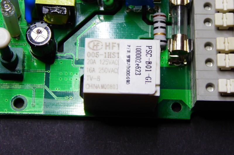
It's hard to say. It burned because something got hot, which usually means there was a high resistance somewhere in the path of the current. Normally I would expect a poor connection where the wires pushed into connectors, or the relay itself burned up (this could happen as repeated switching causes the contacts to carbon up and form a high resistance point). As you probably know, since you referenced that it is an inductive load, induction motors needs 5 times (sometimes more) the nominal power when they start, so as much as 40A when it starts. Since the POW R2 has a 15A relay, this may well be the problem. If it is, I would expect a disassembly of the unit to confirm this: The relay should be totally melted while other pars further away may be less burnt up. Just from the picture, the terminals themselves looks fairly good, and the hole in the case seems to be right about where the relay is... But I also see a somewhat bulky 10Ω resistor in that general area, and a fuse. It could be those too...
-
Well, that was a recommendation for Australia... maybe over there a permanent bond is preferable over a switched one.
-
I'm totally guessing! But it looks (from the photo of the PC board with his thumb on the neutral) as if that terminal is connected to the neutral to the left of it, so that if you merely connect an earth to it, it should apply the bonding we're looking for. @Weasel just needs to confirm. You could probably test it quite easily, doing a few voltage measurements to confirm that it is connected to neutral when running islanded, and disconnected otherwise.
-
What would be really useful is if you could show what unlabelled thing this is and how to wire it, so the guys with the floating supply can rectify their setup. If I read this correctly, you're telling me this terminal: ... actually has a bonding relay attached to it, so you just need to connect an earth to that and it will bond correctly? That's like... seriously.... should be in the manual or something 🙂 Would also be interesting to see if all of them has that. Edit: Finally, someone who knows what they are talking about who can put the matter to bed!

-
Pretty typical issue. Whatever sharp screw is handy is used to mount the plastic plate to the box. Drywall screws for example... and then sometimes that shart point will pierce one of the conductors causing an earth fault. Now if it pierces a live conductor, then usually the breaker trips, or if it is a small leak and the RCD trips, then the problem usually goes away if you turn off the breaker to that circuit. So that kind of fault can be found through a process of elimination by the home owner. BUT... if it pierces a neutral, then the earth leakage trips, and you have NO easy way to find it. You have to isolate the lives and the neutrals in the DB board until you find the one that trips the RCD. An inexperienced DIY homeowner/handyman might conclude that there is something wrong with the RCD... and bypass it. I have my own love/hate relationship with RCDs and modern appliances. Specifically, every $*@#% modern appliance now has a surge arrestor and/or EMI filter, and those things pass current to the earth wire. Small amounts. It is known as the standing loss, and most IT people know about it (too many computers on a circuit, and the RCD starts tripping). So this is how things are in my house right now re standing loss: Now the rules state that 1) you must have a 30mA RCD on plugs, 2) it MUST trip on 30mA residual current , 3) it MAY trip from 15mA onwards. As you can see... sort of surfing on the edge there. But it gets worse. When the inverter's bonding relay opens/closes, I get: Now I have a very expensive RCD installed that is transient resistant, so it does not trip at this level... but if I add one more appliance (the laser printer we bought to home school the kids during COVID19)... it starts tripping every time the power comes back after load shedding. So now I have to split my essentials into two groups with their own RCDs, so I can get the standing leakage down below 10mA again.


-
PV Modules pull down about 15% from their open circuit voltage to the point where they make max power. At the same time, an MPPT will have a maximum input voltage (Voc, aka Voltage open circuit) that should not be exceeded. In most cases, this means that you size the MPPT for a voltage where it rarely spends any time (except early in the morning before it starts up). In addition to that, MPPTs are DC to DC converters, usually a buck converter, but could by buck-boost in some cases (such as this one). The input and output voltage as well as the frequency and output ripple are parameters you design for, and it is most effective within a certain voltage band. So basically what these guys have done, is they designed the DC/DC converter to be efficient up to 500V, but allow a max input voltage of up to 550V, and that is perfectly fine since PV modules pull down somewhat in any case, so it ends well. There is another thing to note though: The MPPTs allow max 11A on the PV side. So if you size your array to 200V or so, you will get max 2000W out of it. You can't put strings in parallel, as that will exceed the current rating (most 300W modules make around 10A already). So to get the full power out of it, you need to put enough modules in series. It's a bit different to other designs where the PV current can be a bit higher.
-
The Multiplus does the same. You can audibly hear it happening when the grid returns after an outage. It shortens the cycles for a short while until the waveforms align and then switches over. It doesn't have to be exact, you just need to be more or less in the same quadrant 🙂
-
Then absolutely check out (for those on FB) the page of his father. Our own Creflo Dollar (look it up if you don't know him).
-
If it is that Salanje guy... you shoud check out his father's fleet of cars. Snazzy! A real Benny-Hinn-esque guy by the looks of it...
-
You're right, for the full 60 you'll need 10mm^2. 6 is going to be a little short.
-
It's probably fine to have it at the end. You'll just have a long 6mm wire going all the way across the top to the left-terminal of the ET112, and then you'll have another 6mm red cable coming back from the right-side top terminal of the ET112 to the top of the busbars on the breakers (not that far this time, right to the left of the ET112). Then on the neutral side, according to the ET112 manual, you're supposed to put a fused connection to the neutral busbar, but you can leave the fuse it with the proviso that this must also be 6mm cable then. Reason for using this oversized cable on the neutral side (even though it only carries the current of the ET112 itself, which is mere MILLIAMPS), is that the cable must always be sized for the upstream breaker, which in this case is the main 63A incoming breaker. It wasn't clear to me that there is space on the right, I was working this entire time under the assumption that (like most people) you don't have enough space to even fit an opinion nevermind a breaker... 🙂 Also, I deliberately put the ET112 after the RCD in this scenario because 1) it does not really matter if you put it before or after, and 2) that allows you to tie the neutral of the ET112 to the neutral busbar post-RCD, which is just so much easier.
-
Well, the RCD would not trip. His house would continue to run (and somewhere in the garden it would be slowly heating some water in the soil where it finds its way back to ground). Then one day you'll be digging in the garden or pulling up a weed and you'll strike/touch the damaged cable. Now you're directly touching a live conductor, and it flows across your heart to your feet and you're dead. If there was an RCD, it would see this 30mA taking a shortcut to earth and it would have tripped, likely saving your life. My dog was likely saved by an RCD. He likes chewing stuff... anything new introduced into his environment. One rainy winter's morning in August 2013, some people came to put blow-in insulation in my roof, and they plugged an extension cord into an outdoor socket... mmmh new chewy toy... That was the most pitiful yelping I've heard in my life... but he stopped chewing things that are attached to the house after that (he still chews anything you leave lying around, especially PVC plumbing stuff).
-
Remember to get minirail to DIN adapters. The ET112 is DIN-mount and won't fit on the Samite rail without the adapter. It needs about 32mm of space in the DB board. The ET112 has both live connectors on top (neutral at the bottom), which makes it fairly easy to install. You'd normally install it directly after the RCD, before any of the other breakers. The live wire looping around from the RCD then enters the top left of the ET112, and the top right of the ET112 connects directly to the top of the breakers next to it. You could ask the electrician to leave some space (if you have it). Sometimes you can also consolidate circuits into one, for example if a breaker is not very heavily loaded and the wire is sized correctly for that breaker, you can put two downstream circuits on one breaker (if the breaker is 20A, then both cables connecting to it must be rated for 20A, etc). More than two circuits is usually not a good idea, too much risk of a poor connection where three conductors are combined. If you have to choose between the geyser timer and the ET112... drop the geyser timer. Those things don't save much money regardless of what the sales person told you. They certainly don't pay back the money you spent on them.
-
You're running without an earth leakage. As long as nobody touches a live conductor (even by accident) you'll be fine. So luck has something to do with it (or the lack of bad luck rather). If you have young kids in the home, I would advise to have this sorted as soon as possible. What I also didn't mention is the way it is wired allows you to disconnect the neutral but keep the Live connected. That could have rather interesting effects on some LED lamps, they may for example glow dimly even though they are supposed to be off. That's an odd way of doing it. You will have to check with an electrician. Usually you only need to isolate the live connector to a water heater, but there must be an isolator (that interrupts both live and neutral) next to it on the roof. But sometimes the rules change. Either way, you can get rid of one of those breakers. The 20A double-pole one has overcurrent protection (green/white lever) so you essentially have two 20A overcurrent protection breakers in series... one of them can go.
-
Aaah no, that has to be done by the Pylontech engineers. And rumour has it the firmware with the new CAN-ids is almost ready for release. You don't need me for that... just hold ear to the proverbial ground at Pylontech 🙂
