___
-
Posts
10,052 -
Joined
-
Last visited
-
Days Won
526
Content Type
Profiles
Forums
Gallery
Blogs
Events
Store
Downloads
Everything posted by ___
-
Right... the number I spat out is for m8. Winston cells Yup, I've also used Vaseline on flooded lead acid terminals. It works well. Not sure it will work in this application though, need something with a little copper/zinc in it that improves conductivity while preventing oxidation.
-
Oh I agree, that seems mighty tight. But I have in my possession the actual construction documentation of a battery maker and that is what they actually use... This forum post suggests that 11Nm is good on an M8 bolt. It depends on the quality of the alloy and of the bolt of course. This shop page says 9Nm. I have never done this before, I merely collected the information so long for a job that has to follow later... once I can source the compound required for the job.
-
The figure I have is 14Nm.
-
I'd go for the US3000. The smaller battery has 2.5kWh storage, of which ideally you should use just 80% or so, and as you can see from the quick number I calculated... you're either going to run out or discharge too deeply each time with the US2500. Go for the larger one, or two of the smaller ones (that would be even better, of course, but carries an extra 10k price tag).
-
Budget off-grid set-up
___ replied to LawrenceJ's topic in Starting In Solar? Feel free to introduce yourself
Swap the battery. It very likely uses something standard, NMC chemistry I would guess. -
You mean this:

-
Re Ripple errors. TTT had me running for days and I kept forgetting that when the BMS disconnect, the capacitors on the DC bus is the only thing holding the ripple down. The ripple, btw, is completely normal and all inverters have it. When shaping a 50Hz AC voltage, it draws current from the battery cyclically, creating a 100Hz ripple on top of the DC. With a nice strong battery this ripple is maybe a 100mV, but when the BMS decides to disconnect, that ripple goes to over 1V and at least Victron inverters will complain about it. Ideally you should keep the cells connected for them to work... Also, I need to say something about dissimilar metals. Please research carefully what you use for the busbars and what bolts you use to tie it down, and ideally also use a torque spanner (suitably insulated of course) to get it right. Watch out for stainless steel bolts, the chromium oxide top layer is not the most conductive. Rather use nickel-plated. You should also consider using some kind of contact compound on the cell terminals. Otherwise you create a high impedance situation which worsens the ripple, but also causes the battery voltage to drop out under relatively low current (eg I have 90Ah 12V batteries here that has this problem, I can hardly get 25A out of them without the voltage dropping out). If anyone knows a good contact paste/compound that you can actually find in this country, let me know. The stuff that I know works really well is Burndy Penetrox A-13, but i can't find it in SA.
-
That battery is good for 35A at around 50V, or about 1.7kW. So as long as you stay under that, you don't need another battery (that of course means the full 5kVA rating of the inverter will never be used). At 400W, plus the roughly 50W or so self-consumption of that inverter, times 4.5 hours, plus a bit of a fudge factor since inverter is not 100% efficient, you're looking at around 2.2kwH discharged from your 3.5kWh battery, or 60% DoD. So it looks okay to me. Edit: Well, I may be a bit hasty in saying you'll be fine. The inverter maker wants a certain amount of battery capacity installed, usually, and this is not only about how much current you can reasonably draw, it would also sometimes be necessary to keep things like ripple down. Also it may affect the warranty. Technically I think you'd be fine, but I'm only about 85% sure
-
You're right! Indeed, I stand corrected. Thanks.
-
It is, it is on page 7 of the 8-page spec sheet, though not marked on the breaker. Normally, for a two pole breaker, one side would be reversed so that you don't have to cross-over the cabling to make it work right (battery on one side, loads on the other), but in this case the breaker was clearly not designed to be used in this manner.
-
Uuuh, no, it won't. In fact, this makes me doubt the experience level of your installer. I'm also concerned about the size of the wire. Those breakers are 12.8mm across. I know you can fit a 25mm^2 to most DIN breakers (16mm wide), so I'm a little concerned about those. Edit: Also polarity. Positive at the top, negative at the bottom. Check that it is installed correctly.
-
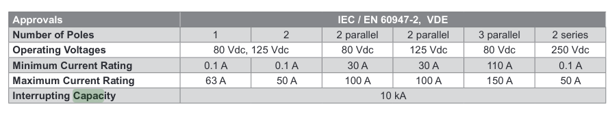
The contacts do have a 10kA interrupting capability according to the spec sheet, and has VDE and a string of other approvals. So this may be okay. The spec sheet also allows for wiring in series to up the voltage rating. I've never been much of a CBI/Samite fan, but I must admit, they make quite decent stuff.
-
To me it looks as if CBI made a 150A breaker by slapping together three 50A breakers. The picture on it shows the internal wiring, or at least how you are supposed to wire it. It's "single pole" in other words. (At this point in the message, imagine I'm going off to google a bit and make sure of my facts..) Aaah yes. Here is the spec sheet. And this is how you're supposed to wire it: If you're not actually using all three contacts in parallel, then it explains your tripping point. Each contact is 50A. 50V*50A = 2500. Spot on. A bit of googling shows that the U2 curve indicated there will trip after around 10 seconds if you go 30% over. So yeah... open up the box and check how it was wired.
-
Wrong shade of blue... looks like JSM power to me... or maybe microcare, not sure
-
I've made my own once in the past. 120Ω resistor crimped into an RJ45 between pins 7 and 8. Throw some heatshrink over it and shrink it down The terminators usually ship with GX hardware, so someone on the forum who bought a Venus-GX or similar but didn't use the canbus side might even have some spares lying around.
-
Of course one could use a buck/boost converter between the banks so they can live at different voltages, but you still get the benefit of using both. But I don't think something commercially available exists for this application. If you had separate PV arrays charging the banks individually (the efficiency would be too dreadful otherwise), and you had a way to move charge from the old lead-acid bank into the LFP bank (using buck/boost, maybe 90% efficient), I think you can make it work. It would be like the buck/boost used in vehicles to charge the second battery from the main one, moving charge from one battery to the other. Edit: Another example would be electric cars that charge their 12V battery from the main HV battery using such converter. Also, this.
-
Commenting a bit on my own writing from yesterday. 1% would be absolutely dreadful in some markets. In the automotive segment for example, 1 in 100 units is a public relations nightmare. Car companies have much lower limits here. One example I sometimes use: You remember Toyota slapped a turbo on the 1KZ engine (around 2002, the 3-liter Diesel)? Now that engine has a reputation for having head problems (valve guides, head gaskets), despite the majority of them having no problems at all in their lifetime. But the margins are tight... The second way is to open one up and look at the components used internally. Even for a layperson, looking at the brand of capacitors they used could be a sign too. If they went with overspec'ed capacitors made by a reputable manufacturer you know an effort was made. That would be makers like Nippon Chemicon, Nichicon, Panasonic, Hitachi perhaps. If you see Jamicon, that still counts as making an effort I think, depending on the specsheet: what is its temperature rating, and how many hours. Early models of the Axpert had Jamicons, but speced at 63V (too low), with 2000 hours at 105°C. If it works hard about 12 hours out of the day, that works out about 6 months, which also what some people reported in the field (look on youtube for a guy called easily bored engineer). In February 2017 Voltronic switched to a Jianghai capacitor, rated at the same temperature for 4000 hours. So by looking at just the caps, I expect on average maybe 2 years out of a hard working unit, but if only used as a UPS during an outage it will probably last 5-10 years. Many people however put two in parallel, and they don't work them to full capacity, hence I estimate 5 years for the average setup before one of the two blows. By that time the Multiplus is just going out of warranty...
-
You can also reset the BMV. If you know the vreg, you can write the state of charge to it, eg: dbus -y com.victronenergy.battery.ttyUSB0 /Devices/0/VregLink SetValue %0xfff '%[0x88, 0x13]' The above will set it to 50%. What is going on there? Well, the % prefix tells the dbus command to interpret what follows as a python literal, so that makes it properly interpret the hex values and constructs a list as the second argument. 0xfff is the vreg for the SOC on battery monitors. And the value itself is a 16-bit value (therefore two bytes) with the LSB first. So the above is 0x13 (19) multiplied by 256 + 0x88 (136) = 5000, which is 50% with two decimals. Why would you use it? Well at least one customer had an issue where on his boat he disconnects everything before transport, and he'd like to put it back to the old values when he reboots next time
-
It's completely different worlds, that's for sure. I find that due to the cost of batteries, there are many people who run their batteries quite close to the top all of the time. Be that as it may, a totally understand that someone would decide to live with this slight inconvenience rather than pay more. In the case of Pylontech, indeed, their BMS is not too bad at this. With some other brands I've heard of people installing a BMV to get a better estimate. BlueNova and BYD, for example, don't measure low current levels very well, so at low power levels you get quite a bit of SOC drift. This is however neither here nor there, because the SOC tracking of a Multiplus also isn't perfectly accurate, so this becomes a bit of a long distance urination contest It is hard to say. I've speculated on this before, that sometimes you can guess the expected life from the warranty the manufacturer slaps on the product. There will be a maximum return rate they are willing to tolerate, for example a typical figure might be 1%, and the warranty is then chosen such that 99% of the units won't fail within the chosen warranty period. So with a 2 year warranty on most of them, it is rather unlikely that it has a 10-year design life. But the above model isn't the only warranty model. Some Chinese televisions use another model: You make it cheap enough that you can sell two for the price of one, and the design life might be even less than the warranty. If the unit fails, you swap it. Since not all of them work equally hard or fail, there is still profit in the overall scheme even if a substantial amount of individual models turns into losses or break-evens. So my thumbsuck is that the Axpert has a 5-year design life. The Victron unit has a 5-year warranty... so the design life has to be more.
-
Correct. Same with capacitors, for example. They come in standard values, 10V, 16V, 25V, 35V, 63V, etc... you buy the next one up from what you need, so if you open a car radio you will see they use 16V caps inside. But sometimes you will see a 25V cap inside a 12V appliance... simply because that's what they had available, or perhaps the price was better. As long as you're rated higher than the expected operating voltage. Correct. But once the fuse melts, there will be a potential difference on either end of it, and that's when the voltage rating comes in.
-
I'm confused. You are allowed to use a higher rating. Just not lower. Unless the cost is prohibitive of course, then you'll buy the least expensive one that still has a high enough rating. As far as I am aware you should have a DC disconnect in the system. If you opt to go for a cheaper fuse (such as a 150A Mega Fuse) on the battery side, that usually means the additional cost of a DC switch to disconnect things. The nice thing about those Mersen fused disconnects is they do both, and the price is not exorbitant.
-
Oh hang on, I see the confusion. I forget that the context here is the EasySolar-II with the MPPT built in. I'm actually not that familiar with that model. I don't have one on my local bench and I always forget what is in it. You usually have to fuse between the Multi and the battery. For this I recommend the big Mersen/Jean Muller fuses, but you can also use a Megafuse/ANL fuse of the correct voltage rating. The reason I prefer the Mersen/JM fuses is that they double as a disconnect. The inverter does not have its own fuses on this side, and you must add your own. If that big fuse blows, it is because something else has already broken elsewhere, and you would prefer to not turn the copper cabling into heating elements But you also have to fuse between the PV modules and the MPPT (which in this inside the inverter), and here I usually use the ceramic 10x38 1000VDC fuses. Much cheaper than Megafuses/ANL. I don't know if there are already fuses inside the inverter, if there are, then I suppose you don't have to fuse another time. Refer to the manual I suppose. I suspect that the engineer will want to see external fuses when he signs off on it. So yeah... sorry... I got confused between battery-side and PV-side fusing. Battery side needs a Mega or Mersen/JM large fuse. PV side can use the smaller ceramic cartridge ones. Battery side needs 60V or so. PV side needs whatever the PV modules put out, but the DC stuff you buy off the shelve is usually rated for 1000VDC.
-
I'm not sure what fuses you are referring to here. The smaller Multiplus units have a built-in fuse, which is just a Megafuse. You open it up and you replace it. from 3kVA up you have to fit external fuses, and Victron specifies fuses that are double what you might expect and slow-blow too. This is because the fuse is there to protect the cable. The inverter itself will switch off to protect itself if there is an overload. The inverter can handle a dead short on the AC side. I've seen a 15kVA repeatedly dead-shorted in an endurance test, running for days on end. When testing overload faults on the smaller inverters, I literally have an AC breaker tied across live and neutral of a 3-point plug... Fuses are largely reacťive rather than proactive protection. By the time they need to blow, something is already badly wrong...
-
Technically they still can't. Well, they can... they have enough hardware to do Amp-hour counting, but it's just not implemented. In the mean time they made it possible to communicate with the BMS in some models, so now the BMS does the SOC accounting so that the inverter doesn't have to. For people with lead acid batteries, it is still true that the inverter does not do proper SOC accounting, unless you employ some external solution (Victron BMV and ICC). I think the point he makes is that in order to really seamlessly drive large loads without the inverter switching back to the grid and potentially losing some PV (cause the batteries are full or close to full) is to AC-tie the PV. Of course when you do that, you lose the PV during a grid outage. This is basically the whole argument for a hybrid inverter... excuse me... a PURE hybrid. Ggnnnh this is like Donald Trump having the twitter handle @realDonaldTrump Nope... this is not always the case. In fact, at any SOC above 85%, where the battery is beginning to fill up and the charge current is reducing, the potential for lost energy is there. The typical situation is this. You have 5kW of PV coming in, and 6kW of load. This exceeds the inverter's capacity, so the inverter switches to the grid. So now the entire 5kW has to go into the batteries, which it will if the battery bank is large and fairly empty, but otherwise the voltage of the battery bank will rise to absorption level within minutes, and the MPPT will start throttling. Now you're in a situation where 5kw of the 6kW of loads could have been offset, but instead 6kW is coming from the grid and the PV is being choked away... Of course you might argue that for the few times a day this happen, the small amount of lost PV can be ignored, especially in the light of the overall cost of the system, and lots of people accept the limitations for that reason too. For me, despite my allegiances and all I think people can easily be penny wise and pound foolish. With the hybrid inverter, your battery bank can be smaller. You can use a smaller LFP bank because you size it only for backup. Warranties on batteries are often shorter when not used with a Hybrid inverter (eg with Dyness). And of course... you will buy at least two Axperts for each Multiplus on average. The design life is just shorter. They can be fixed, they can even be improved slightly as our Ausie friends have proven. But, as I have said before, I really like the Axpert. They turn into future Multiplus sales
-
I always tell people to imagine what happens in slow motion. It's a bit like a dam wall that breaks. First there is just the tiniest bit of a gap, and the energy can still jump across. As long as it jumps across it continues to generate heat and more of the fuse material is melted away, increasing the gap. At the same time the air around the gap is ionized and this makes it easier to jump across. The metal itself can also be vaporised (this is of course much worse with copper!) which also improves the conductivity of the ionized air gap. Now at some point the gap will become too large and the flame will be extinguished. There are some things that happen to speed this up too. With AC current, for example, the fact that the current goes to zero 100 times a second significantly reduces the distance it can jump. If you have some silica around the gap, that also helps to absorb the heat, and the motel silica impedes current flow. While the flame is being extinguished, you also want to keep it from setting other things on fire, and here the silica again helps, but also in some DC breakers there is a magnetic cage that keeps the flame inside the cage. Of course a major factor in how far the energy can jump is the voltage. Generally 1mm for each 100V (a rule of thumb), but of course much further once the air is ionized or you have some vaporized metal in there. You can draw a good 1cm flame from a 200V solar string. You should try it, it is quite the party trick. It's only about 10 amps, but do try not to set things on fire... This is why the fuse has a voltage rating. It has to create a larger gap, and arrest the flame, to interrupt the current flow. And that's why the 60V one is so much more expensive too, compared to the 32V one. The fuse is there to protect the cable. Nothing more. The goodies at the other end has to protect themselves. Quite often, the very reason the fuse has to blow is because the goodie on the other end has already failed